Warning – Duff-Norton NZ-100 User Manual
Page 9
1
2
3
4
5
6
7
8
9
10
11
12
13
14
15
16
17
18
19
20
21
22
23
24
25
26
27
28
29
30
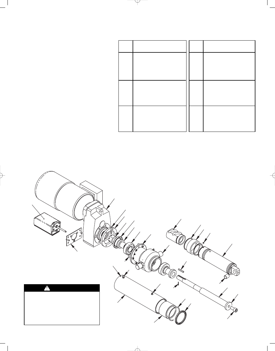
5-1. Part Ientification
The following exploded parts view
shows the components of the Duff-
Norton SuperCylinder. Due to the
wide range of models and
configurations, exact part numbers
are not shown. Some models may
contain additional bushings, rings,
etc. not illustrated in Fig. 5-1. To
order parts, contact Duff-Norton
with the SuperCylinder model
number (example: NZ03-0949-123)
and the item number from the
following illustration. For any motor,
brake, or gearbox part, also include
the serial number from the
nameplate on the gearbox.
SECTION V
ILLUSTRATED PARTS LIST
9
1
Gearbox*
2
Trunnion housing
3
Flange adapter or spacer
4
Load bearing
5
Bearing journal
6
Oil seal or o-ring
7
Slotted hex nut
8
Grooved pin
9
Square key
10
Roll pin
11
Trunnion pin
12
Ball screw
13
Stop washer
14
Stop washer screw
15
Self-lube bushing
Index
No.
Part Name
* - Provide gearbox serial number for brake, motor, or gearbox parts.
16
Translating tube
17
Setscrew
18
Nut guide
19
Spiral ring
20
Ball Nut
21
Outer tube
22
Guide bushing
23
Retaining ring
24
Wiper seal
25
Grease fitting
26
Air vent
27
Setscrew
28
Metric cap screw
29
Limit switch flange
30
Limit switch assembly
Index
No.
Part Name
Figure 5-1. Exploded Parts Illustration
WARNING
Use only replacement parts supplied
by or approved by Duff-Norton.
Non-authorized parts may be
inadequate, resulting in serios injury
or death n event of failure.