Installation – Duff-Norton EM1050-200 (TAP) User Manual
Page 4
4
2-1. Clevis
Connections
Refer to Fig. 1-1 for appropriate mounting
dimensions. The actuator should be connected with
.50 inch diameter steel clevis pins, or bolts with
enough unthreaded length to provide full clevis
support. Lightly grease clevis pins to prevent wear and
noise.
2-2. Motor
Capacitor
All AC units use permanent split capacitor motors
requiring an external motor run capacitor. Capacitor
ratings are listed below.
If actuators are never operated at more than 50% of
rated load, capacitance may be reduced by up to 33%,
resulting in lower current and motor operating
temperature.
2-3. Wiring Connections
All wiring connections for AC units can be made to the
terminal block under the motor cover. Refer to Fig. 2-1
for wiring schematic and Fig. 2-2 for Terminal Block
Connections.
Connections to DC units are made directly to motor
leads. Use wire adequate for the rated motor amps.
Section II
INSTALLATION
Voltage
Rating
Duff-Norton No.
115VAC 50uf,370VAC
SK6405-7-15
230VAC 15uf,440VAC
SK6405-7-14
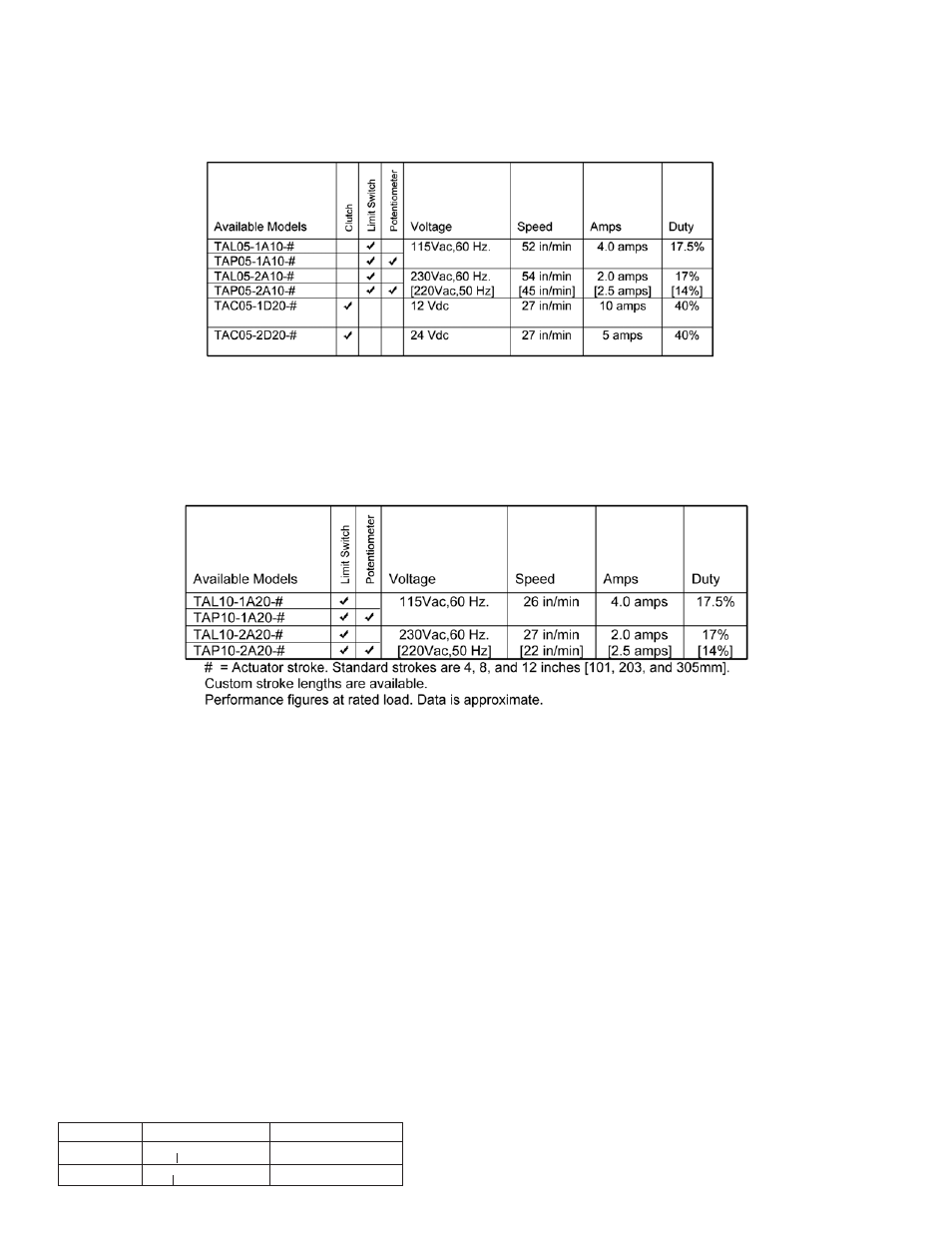
TA500
Performance at Rated Load
TA1000
Performance at Rated Load