1. general, 2. applications, 3. table of specifications – Duff-Norton Ball Screw Translating User Manual
Page 3: 4. important precautions
3
Section I
General Information
1-1. General
This manual contains maintenance instructions
for Duff-Norton translating ball screw actuators. It
describes and details procedures for installation,
disassembly, cleaning, inspection, and assembly of
these actuators.
1-2. Applications
The actuators described and illustrated in this
manual are intended for industrial use only and
should not be used to lift, support or otherwise
transport people unless you have a written state-
ment from Duff-Norton which authorizes the specific
actuator unit, as used in your application, as suit-
able for moving people.
These actuators are intended for a clean, non-
corrosive environment with ambient temperatures
ranging from -20 to 200 ° F. If your environment is
dirty and/or contains abrasive particles it is impor-
tant to protect the screw with a boot. If your atmo-
sphere is corrosive it is important to specify a non-
corrosive material or finish. Duff-Norton can provide
stainless steel, nickel plated or epoxy coated actua-
tors. If your duty is high or your use severe, more
frequent lubrication should be employed. Duff-
Norton publishes a Mechanical Actuator Design
Guide, Catalog No. 2003, which you may find
helpful in the selection and application of mechani-
cal actuators. If you need additional help, please
contact Duff-Norton at (800) 477-5002.
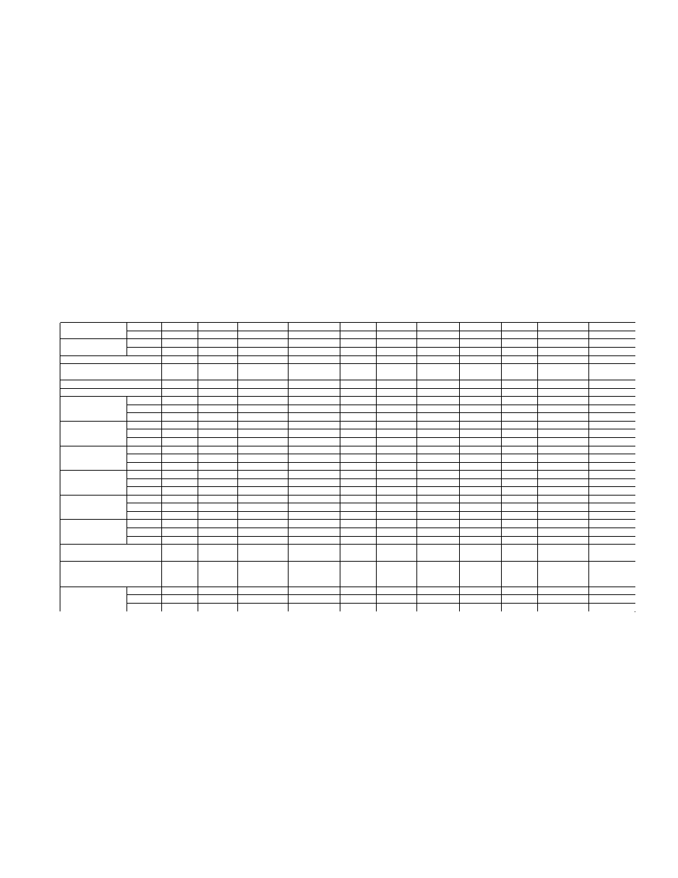
1-3. Table of Specifications
Note: Hold back torque is restraining torque at the worm shaft, to keep load from running down.
*Dimensionally same as Model 2802/9802
† Dimensionally same as Model 9805
‡ Dimensionally same as Model 9810
1-4. Important Precautions
To ensure that actuators provide good service
over a period of years, the following precautions
should be taken:
1. Select an actuator that has a rated capacity
greater than the maximum load that may be
imposed on it.
2. The structure on which the actuators are
mounted should have ample strength to carry
the maximum load, and should be rigid enough
to prevent undue deflection or distortion of the
actuator supporting members.
3. It is essential that the actuators be carefully
aligned during installation so that the lifting
screws are perfectly plumb and the connecting
shafts are exactly in line with the worm shafts.
After the actuators, shafting, gear boxes, etc.,
are coupled together, it should be possible to
turn the main drive shaft by hand. If there are no
signs of binding or misalignment, the actuator
system is then ready for normal operation.
Standard Actuator
Upright
28631
2802/9802
28021/98021*
28003/98003
9805
98051†
9810
98101‡
9820
9825
2860
Model Numbers
Inverted
28630
2801/9801
28011/98011
28002/98002
9804
98041
9809
98091
9819
9824
2859
Special Actuator
Upright
38631
3802/9802
3802/9802
38003/108003
10805
0805
10810
10810
10820
10825
3860
Model Numbers
Inverted
38630
3801/9801
3801/9801
38002/108002
10804
10804
10809
10809
10819
10824
3859
Rated Load (tons)
1/2
2
2
3
5
5
10
10
20
25
50
Diameter of
5/8
1
1
1 11/64
1 1/2
1 1/2
1 1/2
1 1/2
2 1/4
3
4
Lifting Scfew (inches)
.200 Lead
.250 Lead
1.000 Lead
.413 Lead
.474 Lead 1.000 Lead
.474 Lead
1.000 Lead
.500 Lead
.660 Lead
1.000 Lead
Closed Height (inches)
5
7 1/2
7 1/2
9 1/4
10 3/4
10 3/4
10 3/8
10 3/8
16 1/2
19 3/4
25 3/8
Base Size (inches)
2 1/4 x 4
3 1/2 x 7
3 1/2 x 7
3 1/2 x 7
6 x 8
6 x 8
7 1/2 x 8 3/47 1/2 x 8 3/48 1/4 x 11 10 1/4 x 13 3/4 9 3/4 x 19 3/4
Std Ratio
5:1
6:1
6:1
6:1
6:1
6:1
8:1
8:1
8:1
10 2/3:1
10 2/3:1
Worm Gear Ratios
Optional
20:1
12:1
24:1
12:1
24:1
24:1
24:1
24:1
24:1
32:1
32:1
Optional
—
24:1
—
24:1
—
—
—
—
—
—
—
Std Ratio
25
24
6
14.526
12.667
6
16.888
8
16
16.16
10.66
Turns of Worm
Optional
100
48
24
29.052
50.667
24
50.667
24
48
48.48
32
For 1˝ Raise
Optional
—
96
—
58.104
—
—
—
—
—
—
—
Std Ratio
1/3
2
2
2
4
4
5
5
5
8
15
Maximum H.P.
Optional
1/6
3/4
1/2
3/4
3/4
3/4
1 1/2
1 1/2
1 1/2
2 1/2
6
Per Actuator
Optional
—
1/2
—
1/2
—
—
—
—
—
—
—
Starting Torque
Std Ratio
10.5
50
180
110
220
500
350
800
700
925
2,700
at Full Load
Optional
5.0
30
80
68
90
206
175
400
325
475
1,500
(lb-ins)
Optional
—
25
—
50
—
—
—
—
—
—
—
Running Torque
Std Ratio
9.5
45
160
100
180
410
300
700
650
825
2,200
at Full Load
Optional
4.5
25
70
60
80
183
150
290
300
425
1,200
(lb-ins)
Optional
—
20
—
45
—
—
—
—
—
—
—
Std Ratio
65
59
59
59
70
70
65
65
61
60
55
Actuator Efficiency Optional
38
44
33
44
39
39
42
42
44
39
33
Rating (%)
Optional
—
33
—
33
—
—
—
—
—
—
—
Weight with Base
Raise of 6˝ (lbs)
2.75
20
20
21
40
40
50
50
115
235
520
Weight for Each
Additional 1˝ of
Raise (lbs)
0.1
0.3
0.3
0.4
0.9
0.9
0.9
0.9
1.5
2.9
5.0
Hold-Back Torque
Std Ratio
1
2
2
7
8
8
11
11
24
24
92
at Rated Load
Optional
0.5
1
0.5
2
0.5
0.5
0.5
0.5
2
2
33
(lb-ft)
Optional
—
0.5
—
0.5
—
—
—
—
—
—
—