Select a site for the console, Option #1 surface mounting without mounting box, Option # 2 surface mounting with mounting box – Winland Electronics WB800 User Manual
Page 3: Step 1 - power connections, Option 2 - unsupervised probe mode, Step 3 - alarm relay connections, Step 5 - optional remote buzzer connection, Step 6 - setting the audible silence timer, Audible delay, Jumper jp1
S
YSTEM
O
VERVIEW
The WB-800 is a completely electronic water detector which is designed to detect only
nonflammable conductive liquids (distilled and deionized water cannot be detected).
The WB-800 is designed with the control console mounted on the wall and the remote
probes placed in locations where water seepage is most probable.
The unit includes four (4) supervised surface probes (W-S-S). In addition to detecting
water with this probe, the unit will alarm when the supervised probe line becomes
disconnected.
A film of moisture forming a bridge between the two metallic contacts on any remote
probe is all that is needed for the unit to signal an alarm condition (Figure 1). The relay
output is non-latching, but will remain closed until the moisture bridge between the
two contacts is broken. As sensitive as the WB-800 is, it will not alarm due to high
humidity or condensation. The WB-800 is ideal for use around homes, office buildings,
computer rooms, boats, etc. Additional features include:
• Accepts 12V, 24V AC/DC power input
• Eight alarm LED indicators to identify the probe zone in alarm.
• Supervised probe line option. Unit will alarm on open probe condition and an
indicator will light. Up to 8 supervised probes per console (W-S-S or W-UC-S).
Probe lines up to 500ft.
• One “Form C” SPDT Relay for alarm output.
• Built in audible alarm and remote buzzer output with silence feature (adjustable
3 seconds to 150 minutes)
C
ONSOLE
M
OUNTING
C
ONSIDERATIONS
Select A Site For The Console
Probe cable lengths and power source locations should be considered. Maximum cable
length for the water probes is 500 ft.
Option #1 Surface Mounting Without Mounting Box
It is possible to install the console on a soft wall (sheet rock, panel, etc.) without the
use of a mounting box. This is the fastest mounting method and it gives the control
console a nice looking low profile. In selecting a site to mount the console, keep in
mind that it must be placed in a secure, dry location with an ambient temperature
of 32˚ to 130˚F (0˚ to 54˚C). For this option, drill a ½” diameter hole(s) in the wall
which will be opposite the wiring terminal strip on the console. This hole will provide
access for all wiring. Next, carefully mark the location of the four corner screw holes
on the console. Then drive four wall anchors into the proper locations and complete by
attaching the console to the wall.
Option # 2 Surface Mounting with Mounting Box
In areas where no hollow interior walls are available, the included standard 3-gang
surface mounting box can be secured to any wall. The installed profile of the WB-800
with this option is about 2½“ out from the wall.
I
NSTALLATION
- P
OWER
AND
P
ROBE
C
ONNECTIONS
Step 1 - Power Connections
The WB-800 will operate on 12V, 24V AC/DC. Refer to Figure 3 for proper connections.
Note: Before making wire connections, set jumper “JP3” to either 12V or 24V
depending on your power supply output.
Connect your power input to two of the three positions on the terminal block.
Regardless of your voltage input, connect the negative side to “V-“. If your supply is
12V AC/DC or 24VAC, connect the positive side to the position marked “12VAC/DC,
24VDC”. If using 24VAC input, connect to the 24VAC input.
When the power is applied, the green ON power indicator should be on.
Note: If the built-in buzzer sounds, it can be disabled by moving jumper “JP2” to the
OFF position. If desired, toward the end of installation, it can be reactivated.
Important: If you are not using Winland’s 12VDCT power supply accessory with this
product, ensure that your power supply does not have a connection to earth ground.
If the WB-800’s power is connected to earth ground, it’s possible that the sensor will
fail to alarm when wet due to the possibility of a ground loop that may exist from the
sensor terminals through the earth back to the power supply. This will change the
system’s voltage reference, which will, in turn, change its trip point. In all cases, test
the system to ensure it will trip as expected when water is encountered.
Step 2 - Probe Connections
Option 1 - Supervised Probe Mode
The unit includes four supervised surface probes (W-S-S). Additional probes (surface
[W-S-S] or under carpet [W-UC-S]) may be purchased separately.
With no probes attached to unit and with the 8 position DIP switch settings (SW1)
in the down position, zone alarm indicators 1-8 and the probe line alarm indicator
should be on. When the probe line alarm indicator is on, it shows there is an open
probe line. When the zone alarm indicator is on, it shows that a specific zone is in
alarm (either water detected or open probe line).
For zones that are not planned to be used, the supervised mode can be disabled
(i.e. open probe line alarm turned off) by pushing the DIP switches up for the
corresponding zones.
The WB-800 has two terminal blocks (TB1 and TB2) that are the locations for
connecting the probe inputs. There is no polarity to the probes. The probes are
included with 15’ (4.5 m) of cable. The probe cables can be increased to 500’ (152.4
m) with additional cable (22-18 AWG twisted pair, is recommended). Be sure that all
splices are moisture proof.
Note: For probe placement and mounting, see Figures 1 and 2.
Option 2 - Unsupervised Probe Mode
The WB-800 can also be used with the unsupervised surface probes (W-S-U) and the
unsupervised under carpet probes (W-UC-U). These probes are used with Winland
models WB-200 and WB-350. With unsupervised probes, up to two probes can be
connected per zone. However the probe lines are not supervised (i.e. break in probe
lines will not cause an alarm). To use this type of probe the DIP switch zones must be
pushed to the “up” position to disable the supervised probe mode.
Caution: Unsupervised probe mode is only advised if the WB-800 is used to replace
an existing model such as the WB-200 when existing probes are planned to be
used. Unsupervised probe mode may also be used when more than eight probes are
required for the application. To take maximum advantage of the WB-800, supervised
probes are recommended.
Step 3 - Alarm Relay Connections
The WB-800 includes one Form C (SPDT) Relay. This relay is activated when power is
applied and the unit is not in water detect or open probe mode. This feature provides
power-on supervision in case of power loss.
Note: When power is applied and unit is not in alarm, a short exists between “NC” and
“C”, and an open exists between “NO” and “C”.
Step 4 - Installation- Audible Alarm and Silence Features
The WB-800 has a built-in audible alarm which will sound on an alarm condition. An
audible silence feature is included that will disable the buzzer for a time period that
can be set from 3 seconds to 150 minutes. This feature is important in installations
where a constantly sounding alarm might disrupt business. It allows the audible alarm
to be suspended while you wait for the water to be cleared from the affected probe.
Note: During this time, the alarm indicators and the relay outputs will remain in
alarm condition as long as unit is still in an alarm condition.
Note: Jumper “JP2” can be set to enable or disable the built-in buzzer.
Step 5 - Optional Remote Buzzer Connection
The WB-800 is capable of driving an external 12VDC buzzer (BZ-1). The buzzer is
connected to the terminal block as per Figure 3. As with the built-in buzzer, the
remote buzzer can be temporarily disabled by the audible silence feature.
Step 6 - Setting the Audible Silence Timer
The built-in audible silence timer provides an external means of silencing the audible
alarm for a user selectable period (3 seconds to 150 minutes). Set jumper “JP1” to
seconds or minutes. Adjust “Audible Delay” to the number of seconds or minutes
desired.
Note: If a great amount of accuracy is required in setting the number of minutes, the
jumper should first be placed in the seconds mode and then force the unit to alarm.
The number of seconds the audible alarm was silenced corresponds to the number of
minutes. When satisfied with setting, place JP1 back to minutes position.
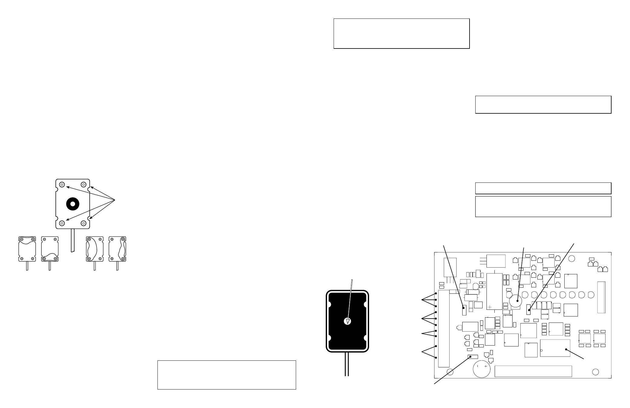
Figure 1
WATER
WATER
W
ATER
W
ATE
R
ALARM
NO ALARM
Four Probe Contacts
Mount the probe to
ensure these four
stainless steel contacts
are against the surface
to be monitored.
F
IGURE
3
Important: Before applying power,
make sure Jumper 3 “JP3” is in the
proper position.
12V or 24V
Audible delay:
Adjustable from 3-150
seconds or minutes -
depending on JP1 position.
24 VAC
V -
N/C
C
N/O
+
-
S1
S1
S2
S2
12V
24VDC
S3 S3 S4
S4
S5
S5
S6
S6
S7
S7 S8 S8
LED
9
LED
8
LED
7
LED
6
LED
5
LED
4
LED
3
LED
2
LED
10
LED
1
Push SW1
up to disable
supervised probe
input mode.
SW1
Zones
1 2 3 4 5 6 7 8
Probe Input Zones 3 - 8
BZ-1
JP2
On
Off
Buzzer
Select
Volts
12V
24V
JP3
Sec
Min
JP1
Buzz
er D
ela
y
Jumper JP1
Silence delay set for
minutes or seconds.
12, 24 V AC/DC Input
Note: Separate
positions for 24 VAC
Relay OUT
External Buzzer +
External Buzzer -
(25mA max)
Probe Input Zones 1-2
Jumper JP2
Left = Built in buzzer “Off”
Right = Built in buzzer “On”
Caution: If a supervised probe is used, and the zone DIP switch is inadvertently left
in the “up” position (supervised mode disabled) the probe will still be operational to
detect water, however, the open probe line alarm will not be operational. Verify the
DIP switch is in the “down” position for zones being used.
Important: Upon completion of a supervised probe installation, disconnect the
probe line from the terminal block to verify the probe line and zone indicators light
(alarm). The unit should go into alarm within approximately 3 seconds.
Caution: Use only the BZ-1 buzzer due to the units extremely low current draw.
Using another buzzer may affect the performance of the WB-800.
To insure proper operation, test weekly.
Drill only in the
innermost area.
F
IGURE
2
Concrete can be semi-conductive. If experiencing false alarms,
insulate all probes mounted on concrete.