Step 1: connect power and probe(s), Step 2: unlock console for programming, Step 3: set the time and date – Winland Electronics EA200 User Manual
Page 3: Step 4: program the zone(s), Step 5: alarm wiring, Step 6: test the system, Additional features, Power requirements, Offset button, Alarm history button
STEP 1: CONNECT POWER AND PROBE(S)
Connect power to the PWR IN terminals, as shown in Figure 1. Be sure to observe proper polarity. Connect the probe(s) to the
zone(s) you intend to monitor. Extend the length of probe wiring up to 1,000’ (304.8m) using 22-18 AWG twisted pair.
EA200 NOTE:
Zone 1 is dedicated for the on-board temperature sensor. Remote probes must be programmed on Zone 2.
There is only one input for a remote probe on the EA200 - this is Zone 2.
EA400 NOTE:
The EA400 does not have an on-board temperature sensor and uses only remote probes.
STEP 2: UNLOCK CONSOLE FOR PROGRAMMING
To unlock the console, press and simultaneously release the ENTER and ALARM SILENCE buttons. The
“lock” icon should change to “unlocked”.
STEP 3: SET THE TIME AND DATE
Press the TIME/DATE button. Using either the INCREASE or DECREASE button, adjust the hours and then press the ENTER
button. Continue in this manner to set the minutes, AM/PM, year, month, and day. If power is lost, the time and date must
be reset.
STEP 4: PROGRAM THE ZONE(S)
1. Press the ZONE button. The active zone number will be flashing.
2. Select the zone you wish to program using INCREASE or DECREASE and then press ENTER. The “no”
means “not operational” and indicates the zone is currently off. Any zone not programmed should
be set to “no” and therefore turned off.
3. Based on the chart (Figure 2), select the proper sensor type using INCREASE or DECREASE and press ENTER.
4. Continue in this manner to set the
• high limit
• low limit
• optional time delay in minutes (this defaults to 0)
• non-alarm relay state (ENERGIZE/DE-ENERGIZE)
NOTE:
If you are powering this device
from a system with battery back-up,
DE-ENGERGIZE (the default) generally
makes the most sense. If an alarm
is desired upon loss of power to the
EnviroAlert, select ENERGIZE. However,
the normally-open (N.O.) and normally-
closed (N.C.) contacts shown in Figure 1
will then be functionally opposite.
STEP 5: ALARM WIRING
You have the option of using the AUX
relay for all-in-one notification or using
the individual relay outputs. The AUX relay will change state when any zone is in alarm and can be cancelled for 10 minutes
using the ALARM SILENCE button. The individual outputs are not affected by the ALARM SILENCE button.
NOTE:
If you are using the individual relay outputs, Output 1 corresponds to Zone 1; Output 2 corresponds to Zone 2; etc.
See Figure 1.
STEP 6: TEST THE SYSTEM
Test the system to ensure proper operation prior to leaving the job site. To test the system, either change the probe’s
temperature so it exceeds your limits, or change the limits to simulate an alarm. If a delay has been programmed, take the
delay out, test the unit, and then put the delay back in.
ADDITIONAL FEATURES
OFFSET button:
The EnviroAlert has the ability to adjust the displayed temperature reading for each zone to match to
a known-good reference (±9 degrees). To use this feature, press the OFFSET button, choose which zone you wish to offset,
press ENTER, adjust the value of the offset, and then press ENTER again.
ALARM HISTORY button:
This will display the most recent eight alarm events. The display will toggle between
the time and date. To scroll through the alarm events, use the INCREASE or DECREASE buttons. Press the ALARM HISTORY
button again to exit. This feature relies on the time and date being set correctly. To clear the alarm history, press and hold the
ALARM HISTORY button until you see “CLr”.
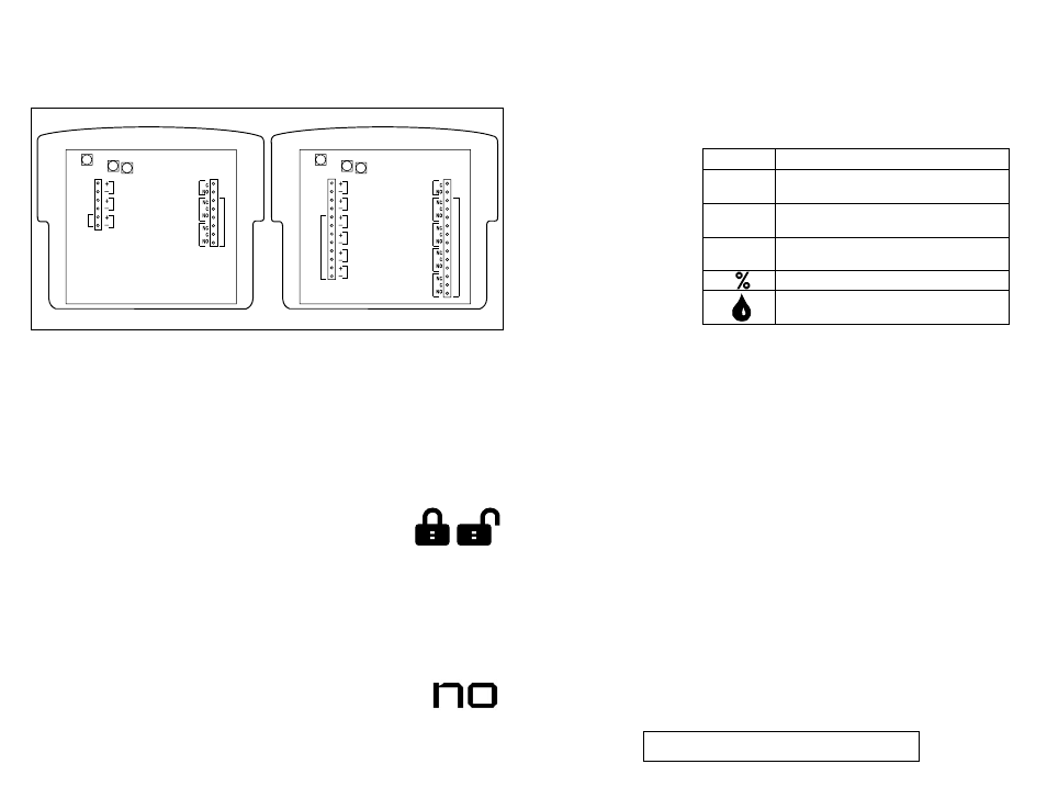
Figure 1 - EA200 and EA400 Wiring
POWER REQUIREMENTS:
EA200-12: 11 to 14 VDC @ 120mA
EA400-12: 11 to 14 VDC @ 200mA
EA200-24: 23 to 26 VDC @ 120mA
EA400-24: 23 to 26 VDC @ 200mA
AUX OUT
Zone 1
PWR IN
PWR OUT
Zone 2
REMO
TE PROBE INPUT
AL
AR
M
OU
TP
UT
S
(On-Board
Sensor)
Zone 2
(External
Probe)
EA200
AUX OUT
Zone 1
Zone 2
Zone 3
Zone 4
PWR IN
PWR OUT
Zone 1
Zone 2
Zone 3
Zone 4
REMO
TE PROBE INPUT
S
AL
AR
M
OU
TP
UT
S
EA400
Lock Unlock
Probe Type
Description
°C or °F
Legacy (discontinued) polarity-sensitive temperature probes
1106, 1107, 1108, 1109, 1109A
Red °C or
Red °F
TEMP-H-S (32° to 300° F) and TEMP-H-W (32° to 221° F)
High-temperature range thermistor probes
Blue °C or
Blue °F
TEMP-L-S (-58° to 158° F) and TEMP-L-W (-58° to 158° F)
Low-temperature range thermistor probes
HA-III+ Humidity probe (5 to 95 % RH)
W-S-S and W-UC-S
Water detection probe (surface and under-carpet) supervised
Figure 2 - Remote Probe Selections
To insure proper operation, test weekly.