Alarm contacts – WIKA 632.51+8xx User Manual
Page 8
WIKA Operating instructions pressure gauges Model 63.51 with 831 per ATEX
8
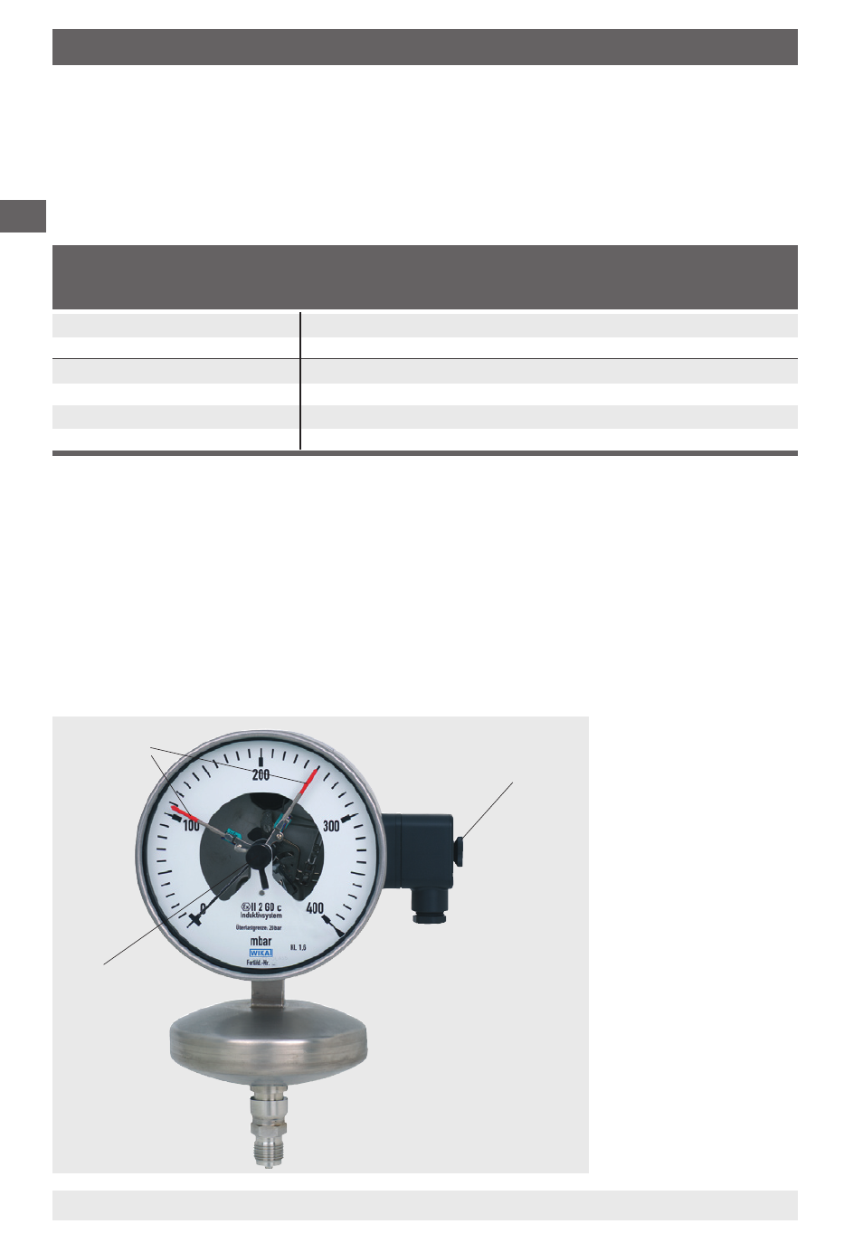
Red set
pointers
Adjustment
lock
Adjustment key
removable
The red set point-
ers for the alarm
contacts are ad-
justable over
the full range
of the instrument.
Switching points
shall be set in the
ranges between
10 % and 90 %
of the scale, to
ensure switching
accuracy and long
life of the
mechanical
measuring
system.
11059738
11/
008
GB/D/F
GB
The permissible limits for U
i
, I
i
and P
i
of the intrinsically safe supply circuits
depend on the sensor type. They can be taken from the corresponding EC-
type examination certificates. (The sensor type is stated on the connection
plate of the pressure gauge.)
Suitable switch amplifiers are e.g.:
4. Alarm contacts
Circuit
Sensor type Model designation
EC-type exami-
WIKA-
(s. Ex-certific.)
Fa. Pepperl & Fuchs nation certificate
Model
Model 1
standard
KFD-SR-Ex1
PTB 00 ATEX 080
904.31
standard
KFD-SR Ex
PTB 00 ATEX 080
904.3
Model 2
standard
KFA6-SR-Ex1
PTB 00 ATEX 081
904.8
standard
KFA6-SR-Ex
PTB 00 ATEX 081
904.9
SN-sensors
KFD-SH-Ex1
PTB 00 ATEX 04
904.33
SN-sensors
KHA6-SH-Ex1
PTB 00 ATEX 043
904.30
Electromagnetic compatibility
EMC according to EN 60 947-5-.
The instruments are to be protected against strong electromagnetic fields.
To adjust red set pointers
The red set pointers for the alarm contacts are adjustable over the adjustment
lock in the window with the aid of adjustment key (included in delivery; to be
found on standard gauges on the outside edge of the junction box).