DuraVent FasNSeal W2 Double-Wall User Manual
Page 8
8
opening, gas utility meter, service regulator or
the like. It also shall terminate at least 3’ (.9m)
above any forced air inlet within 10’ (3.1m)
and shall terminate at least 4’ (1.2m) below, 4’
horizontally from or 1’ (.3m) above any door,
window, or gravity air inlet into any building as
provided in the National Fuel Gas Code aNSI
Z223.1 and NFPa 54. Proper judgement may
require greater distances depending on the
size of the equipment installed or to allow for
snow drifting or falling from overhead roofs or
trees. the termination should be far enough
away from trees, shrubs or decorative items to
prevent damage.
• the total vent length from the appliance
flue collar to the outside termination shall not
be greater than specified in the appliance
manufacturer’s instructions.
• a horizontal installation shall have a slope
(upwards or downwards for Category II, III, or
IV appliances) of no less than 1/4” (6.4mm)
every 12” (305mm) to prevent collection of
condensates, formation of ice build up, or
blockage at any location within the assembly.
Refer to appliance manufacturer’s installation
instructions for further details regarding the
installation of condensate drain fittings and the
pitch of the system.
• Use non-combustible hanger straps a
minimum of every 6’ (1.8m) to support the
vent system from ceiling joints or other solid
structures. Do not puncture the vent system!
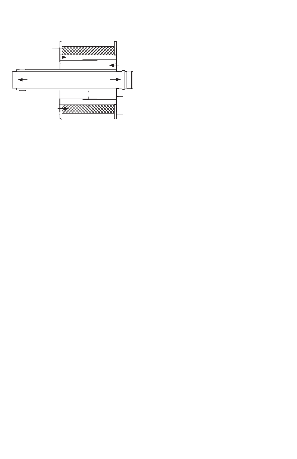
1. Determine the location and install the Wall
thimble so that a continuous minimum slope
of 1/4” per foot is maintained in any horizontal
portion of the vent system.
Condensate must flow freely and may not
be retained in any part of the vent system.
2. Cut the opening for the Wall thimble to
allow the spacer tabs protruding from the outer
plate to sit comfortably within the opening.
(See Wall thimble Installation diagram)
• NOTE: the opening for the W2 Wall thimble
will be 6-inches larger than the vent diameter,
e.g. 3” vent system will need an wall opening
of 9” to allow spacer tabs to rest within the
opening.
3. Position Part a into the opening so that the
gasketed end of the Wall thimble is located on
the outside of the structure.
4. apply a bead of silicone between the two
surfaces and around the edges before nailing
or screwing the plate on Part a to the outside
of the structure.
5. From the inside, slide the sleeve of Part B
onto the sleeve of Part a until Part B’s plate
is flush against the inside structure surface.
Fasten with screws or nails.
• NOTE: When terminating through a non-
combustible wall, the wall thimble is optional.
6. Use a termination tee or a Birdscreen to
finish the system’s exterior.
7. When the vent system must pass through
an interior wall, use a Wall Pass through
(FSWPt). Cut the same size hole for the
FSWPt as was cut for the Wall thimble and
install using the same method.
8. assemble FasNSeal W2 from the appliance
towards the Wall thimble. Refer to “Joint
Connections” in these installation instructions
Wall Thimble Installation
OuTSide
BuiLding
SurFAce
inSide BuiLding
SurFAce
PArT B
1.0”
PArT A
1.5”
TO TerminATiOn
4.3” - 8.6”
2” x 6” STud
(cOmBuSTiBLeS)
TO APPLiAnce