Fig 10, Figure 8, Figure 9 – M&G DuraVent Combustion Air Systems User Manual
Page 8: Figure 10
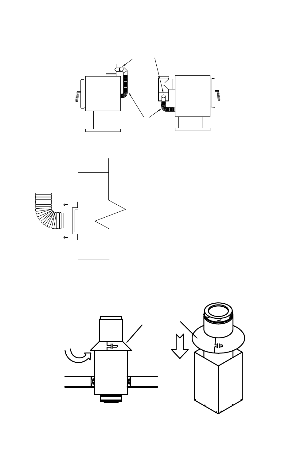
Fig 10
Tighten collar around
chimney section.
Slide collar down to
rest on top of Ceiling
Support
Air must be allowed
to flow under collar
into Ceiling Support.
Do not seal openings
between collar and
Ceiling Support
8
of the Adapter. Additional lengths of CAS
Connector pipe can then be installed using the
screws provided to secure the pipe lengths
(male end up, female end down) (Fig 7). A
Telescoping Length will likely be needed. The
final CAS Connector Pipe section is installed
into the bottom of the CAS Ceiling Support and
secured using (3) 3/8” screws provided.
CAS Telescoping Lengths are
available to provide adjustment in the
connector pipe. The CAS Telescoping Length
are available in 14”-24”, 29”-46”, or 40”-68”
sizes. Once the adjustable length is at the
ATTACH ELBOW TO BRANCH
OF ADAPTER WITH (3) SCREWS
PROVIDED.
Figure 8
ATTACH FLEx TO STOVE
AND ELBOW USING HOSE
CLAMPS PROVIDED
Figure 9
ATTACH FLEx ADAPTER
OVER STOVE AIR INLET
BY USING (4) SCREWS.
SECURE FLEx TO
FLEx ADAPTER BY
USING HOSE CLAMP
PROVIDED.
TIGHTEN COLLAR AROUND CHIMNEY
SECTION. SLIDE COLLAR DOWN TO
REST ON TOP OF CEILING SUPPORT.
AIR MUST BE ALLOWED TO
FLOW UNDER COLLAR INTO
CEILING SUPPORT. DO NOT
SEAL OPENINGS BETWEEN
COLLAR AND CEILING
SUPPORT.
Figure 10