Duraplus htc chimney cas installation, General installation requirements, 5framing dimensions – DuraVent Combustion Air Systems for DuraPlus HTC User Manual
Page 5
5
Framing Dimensions
COMPONENT
6"
DIAMETER
8"
DIAMETER
Duraplus htc
CAS CEILING SUPPort
14-1/2"
14-1/2"
CAS wALL thImbLE
14-1/4"
14-1/4"
DURAPLUS HTC CHIMNEY CAS
INSTALLATION
The DuraVent Combustion Air System (CAS) can
be used with both vertical (through-the-ceiling)
and horizontal (through-the-wall) DuraPlus
HTC chimney installations. The CAS system
is designed to be used with stoves that have a
specific air-inlet on the back of the stove. Verify
the stove you are using has an air-inlet to which
the CAS system can be attached.
GENERAL INSTALLATION
REQUIREMENTS
These CAS installation instructions are intended
to be used with the full installation instructions
for DuraPlus HTC. Except as described in
these installation instructions, always follow the
DuraPlus HTC installation instructions for a safe
installation. These CAS installation instructions
describe how to connect the CAS system to
DuraPlus HTC chimney systems, and how to
connect the CAS system to the stove. In order
for the CAS system to be function properly, the
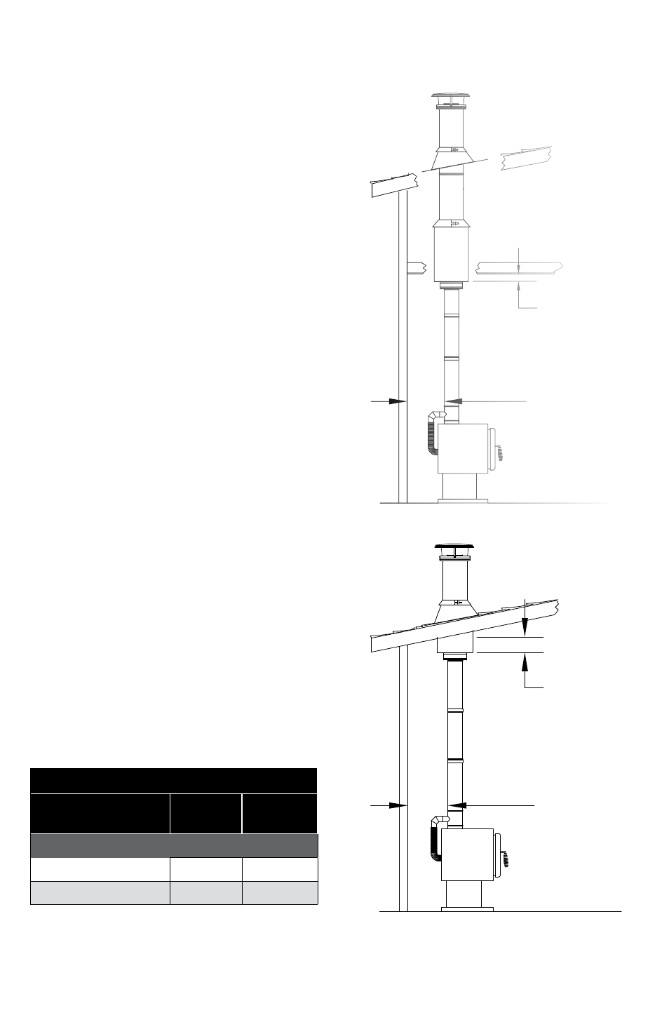
system needs access to outside air. The outside
air is intended to come through the ventilated
attic space or flashing (through-the-ceiling
installations, Fig 1 & 2) or through the chase
(through-the-wall installations, Fig 3).
Table 1
Figure 1
Figure 2
SqUARE
PORTION
OF CEILING
SUPPORT MUST
BE AT LEAST
3" BELOW
FINISHED
CEILING
SHORT SIDE OF
CEILING SUPPORT
MUST BE AT LEAST
3" BELOW FINISHED
CEILING
MAINTAIN
AT LEAST 6"
CLEARANCE
BETWEEN CAS
STOVE PIPE AND
WALL
MAINTAIN
AT LEAST 6"
CLEARANCE
BETWEEN CAS
STOVE PIPE AND
WALL