Figure 8 figure 9, Figure 7a – DuraVent DuraPlus HTC User Manual
Page 10
10
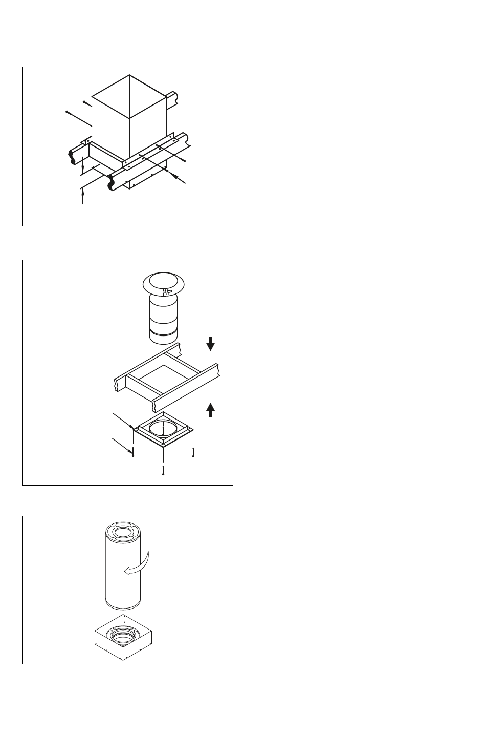
section, with the bead resting on the circular
opening in the plate (Fig 8). Slide the Collar
down on top of the Radiation Shield to
complete the Firestop Radiation Shield
installation.
For 6" diameter chimney, a Reduced
Clearance Firestop Radiation Shield is
available. This Firestop has the same
dimensions as the Reduced Clearance
Support Box, so it can fit between tight
framing members. Important: the 2"
minimum clearance to combustibles
must still be maintained for the rest of the
installation (other than the framing for
the Reduced Clearance Support Box and
Firestops), including the chase enclosure
between the Support Box and the Firestop.
7. Assemble Chimney Sections: Lower
the female end of the first Chimney Section
in the Support Box (Fig 9). It will twist-lock
clockwise onto the male end of the Support
Box. Turn Pipe Sections firmly clockwise 1/8
of a turn to lock them together. Sheet metal
screws are not required, but they may be
used to reinforce the connection, if desired.
Use only 1/2” (13 mm), or shorter, stainless
steel sheet metal screws. Do not penetrate
the inner liner of the chimney.
8. Install Attic Insulation Shield: In the attic
space, one of the following methods must be
used to prevent the chimney from contacting
attic insulation:
1. Use the Ceiling Support Box with Collar
2. Use Firestop Radiation Shield with Collar
3. Fully enclose the chimney through the attic
(maintain 2" minimum clearance).
DuraPlus HTC uses either a tall Cathedral
Ceiling Support Box with an Attic Insulation
Collar or a Firestop Radiation Shield with
its own Collar to act as an attic insulation
shield (Fig 10). If needed, the Attic Insulation
Collar can be trimmed to fit between framing
members, as long as it still covers the Support
Box or Firestop Radiation Shield. The Support
Box or the Firestop Radiation Shield must be
Figure 8
Figure 9
TWIST CHIMNEY
SECTION CLOCKWISE
TO LOCK INTO
SUPPORT BOx
Figure 7A
INSTALL RADIATION SHIELD
FROM ABOVE SO BEAD
RESTS ON FIRESTOP. ADjUST
ExTENSION SHIELD SO TOP
IS ABOVE LEVEL OF ATTIC
INSULATION. PUSH COLLAR
DOWN ONTO ExTENSION TUBE.
FRAMED OPENING
(SEE TABLE 2)
INSTALL
FIRESTOP
BELOW
FRAMING
WOOD
SCREWS
(4 REq)
MIN. 3"
(75MM)
BELOW
FINISHED
CEILING
SECURE
GUIDE
RAILS TO
SUPPORT
BOx WITH
SHEET
METAL
SCREWS