Table 4 – Kramer Electronics TP-46 User Manual
Page 11
Your Component/XGA – Audio Transmitter and Receiver
9
Table 4: TP-46 Component/XGA – Audio Receiver Features
#
Feature
Function
1
XGA OUT 15-pin HD (F)
Connector
Connect to the XGA acceptor
2
LINE IN RJ-45 Connector
Connect to the LINE OUT RJ-45 connector on the TP-45
3
LINE OUT RJ-45 Connector
Connect to the LINE IN connector on an additional TP-46
4
12V DC
+12V DC connector for powering the unit
5
OUTP
UTS
ANALOG AUDIO 3.5mm
Mini Connector
Connect to the stereo analog audio acceptor
6
S/PDIF RCA Connector
Connect to the digital audio acceptor
7
Y RCA Connector
Connect to the component video acceptor
8
C
B
/P
B
RCA Connector
9
C
R
/P
R
RCA Connector
10
LINK LED
Lights when receiving the correct input signal
11
ON LED
Lights when receiving power
and
define the underside of the TP-46:
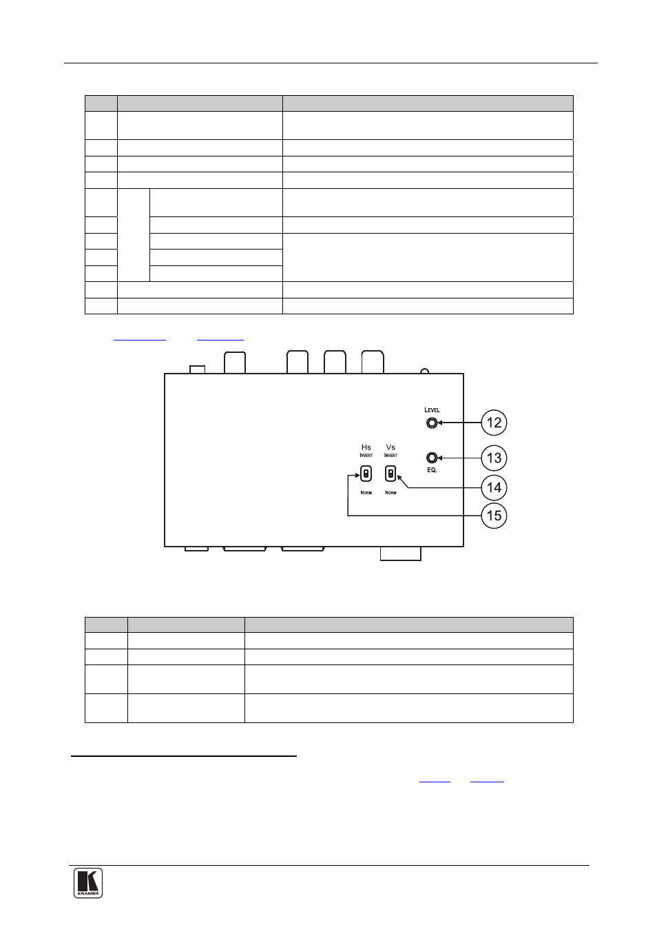
Figure 5: TP-46 Component/XGA – Audio Receiver (Underside)
Table 5: TP-46 Component/XGA – Audio Receiver (Underside) Features
#
Feature
Function
12
LEVEL Trimmer
Adjusts
the output signal level
13
EQ.
Trimmer
Adjusts
the cable compensation equalization level
14
VS Switch
Slide the switch down (to NORM) to retain the polarity
Slide the switch up
(to INVERT) to invert the VS polarity
15
HS Switch
Slide the switch down (to NORM) to retain the polarity
Slide the switch up
(to INVERT) to invert the HS polarity
1 Using a UTP cable with CAT 5 connectors at both ends (the PINOUT is defined in
Table 6
and
Figure 9
)
2 Use a screwdriver to carefully rotate the trimmer, adjusting the appropriate level
3 Degradation and VGA/XGA signal loss can result from using long cables (due to the effects of stray capacitance, for
example), sometimes leading to a loss of sharpness in high-resolution signals
4 By default, both switches are set to NORM