4 your sl-1 master room controller, Your sl-1 master room controller, Figure 1: sl-1 master room controller – Kramer Electronics SL-1 User Manual
Page 6: Table 1: sl-1 master room controller functions, 4your sl-1 master room controller, Figure 1 and table 1 define the unit
KRAMER: SIMPLE CREATIVE TECHNOLOGY
Your SL-1 Master Room Controller
4
4
Your SL-1 Master Room Controller
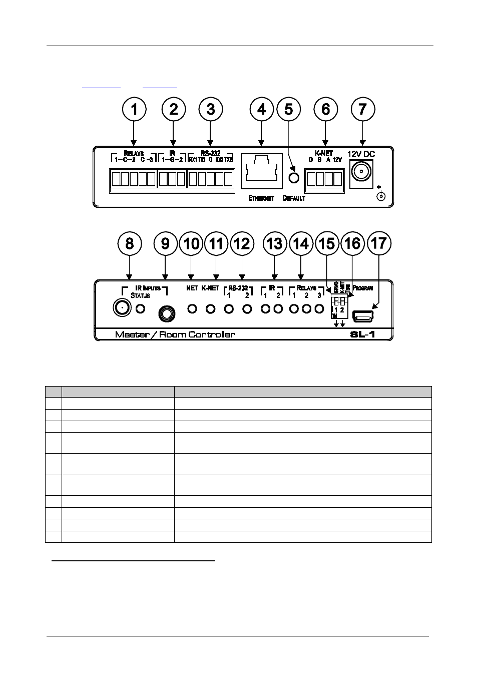
Figure 1: SL-1 Master Room Controller
Table 1: SL-1 Master Room Controller Functions
#
Feature
Function
1
RELAYS Terminal Blocks
Connect to low-voltage relay-driven devices (from 1 to 3)
2
IR Output Terminal Blocks
Connect to IR emitter cables (from 1 to 2)
3
RS-232 Terminal Blocks
Connect to the RS-232 devices (from 1 to 2)
4
ETHERNET RJ-45 Connector Connects to the PC or other serial controller through computer networking
LAN
5
DEFAULT Pushbutton
Press to reset to factory default definitions
6
:
IP number
− 192.168.1.39, mask – 255.255.0.0, gateway – 0.0.0.0
K-NET
PIN GND is for the ground connection
Terminal Block
7
; PIN B (-) and PIN A (+) are for
RS-485, and PIN +12V is for powering the unit
12V DC Connector
For supplying power to the unit
8
IR IN Sensor and LED
Accepts IR remote commands
9
IR INPUT 3.5mm Mini Jack
Connects to a remote infrared sensor
10 NET LED
Illuminates when the Ethernet link is active
1 First disconnect the power cord and then connect it again while pressing the ETH Factory Reset button. The unit powers up
and loads its memory with the factory default definitions and erases all stored presets
2 K-Net is a proprietary Kramer protocol for interconnecting Kramer units
3 The ground connection is sometimes connected to the shield of the RS-485 cable (in most applications, it is not connected)