1 the k-net pinout, 2 the rs-232 pinout, The k-net pinout – Kramer Electronics PL-8 User Manual
Page 9: The rs-232 pinout, Figure 4: wiring the k-net connector, Figure 5: rs-232 pinout connection, Table 3: rs-232 pinout connection, Section 5.2, Configuring the pl-8 low voltage relay controller, Rs-232 pinout
KRAMER: SIMPLE CREATIVE TECHNOLOGY
Configuring the PL-8 Low Voltage Relay Controller
6
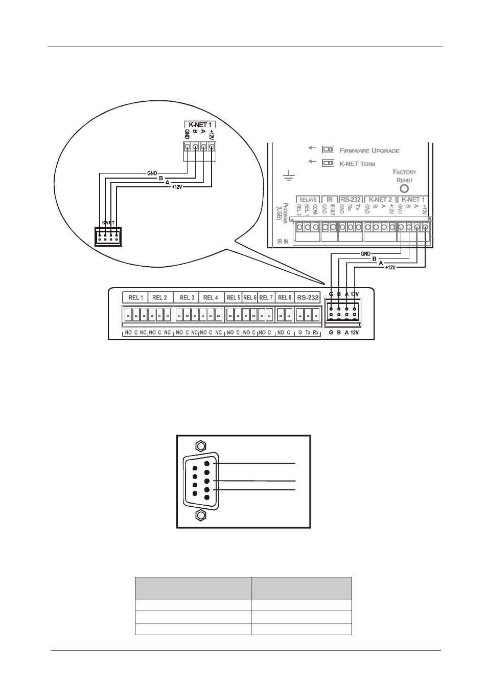
5.1 The K-NET PINOUT
Figure 4 defines the K-NET™ PINOUT:
Room Controller
Black = GND
PINOUT
Red = +12V
Green = A
White = B
Figure 4: Wiring the K-NET Connector
5.2 The RS-232 PINOUT
The RS-232 9-pin D-sub port PINOUT is defined in Figure 5 and Table 3:
RS-232 PINOUT
Rx
GND
1
2
3
4
5
6
7
8
9
Tx
Figure 5: RS-232 PINOUT Connection
Table 3: RS-232 PINOUT Connection
Connect this PIN on the
Terminal Block Connector:
To this PIN on the
9-pin D-sub Connector
Tx
PIN 2
Rx
PIN 3
GND
PIN 5