Figure 2: pl-8 underside, Table 2: underside features, Instead of “p – Kramer Electronics PL-8 User Manual
Page 7: And “p, Instead of “rs-485 t
KRAMER: SIMPLE CREATIVE TECHNOLOGY
Your PL-8 Low Voltage Relay Controller
4
Table 1: PL-8 Low Voltage Relay Controller Features
#
Feature
Function
1
REL Terminal Block (from 1 to 4) Connect to room items
2
. The PINOUT is: NO: Normally Open;
C: Common Voltage; NC: Normally Closed
REL Terminal Block (from 5 to 8) Connect to room items
. The PINOUT is: NO: Normally Open;
C: Common Voltage
3
RS-232 Terminal Block
Connects to the RS-232 port on a PC
4
K-NET™
PIN GND is for the Ground connection
Terminal Block
Connector
5
; PIN B (-) and PIN A
(+) are for RS-485, and PIN +12V is for powering the unit
LINK LED
Illuminates when a link is established
6
ON LED
Illuminates when receiving power
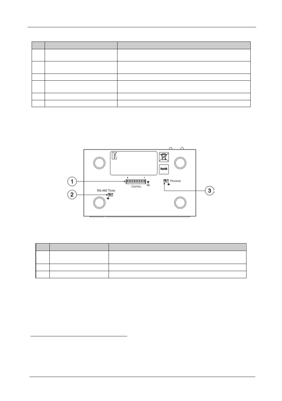
Figure 2 and Table 2 define the underside of the PL-8. On some units the
printing of the labels “RS-485 T
ERM
” (instead of “P
ROGRAM
”) and
“P
ROGRAM
” (instead of “RS-485 T
ERM
”) may be swapped around
erroneously. The correct labeling is defined in Figure 2 and Table 2.
Figure 2: PL-8 Underside
Table 2: Underside Features
#
Feature
Function
1
CONTROL DIP-switches
Set DIP 8 ON to use protocol 2000
Set DIP 8 0FF to use protocol 3000 over K-NET™
2
RS-485 TERM Switch
Switch for line termination of the unit
3
PROGRAM Switch
Switch to PROGRAM for firmware upgrade
1 Such as lighting, screen settings, blinds, and so on
2 K-NET is a proprietary Kramer protocol for interconnecting Kramer units
3 The ground connection is sometimes connected to the shield of the RS-485 cable (in most applications, it is not connected)
4 DIPs 1 to 7 are not used