Kramer Electronics VP-200AK User Manual
Page 7
Connecting the VP-200AK 1:2 UXGA / Audio DA
5
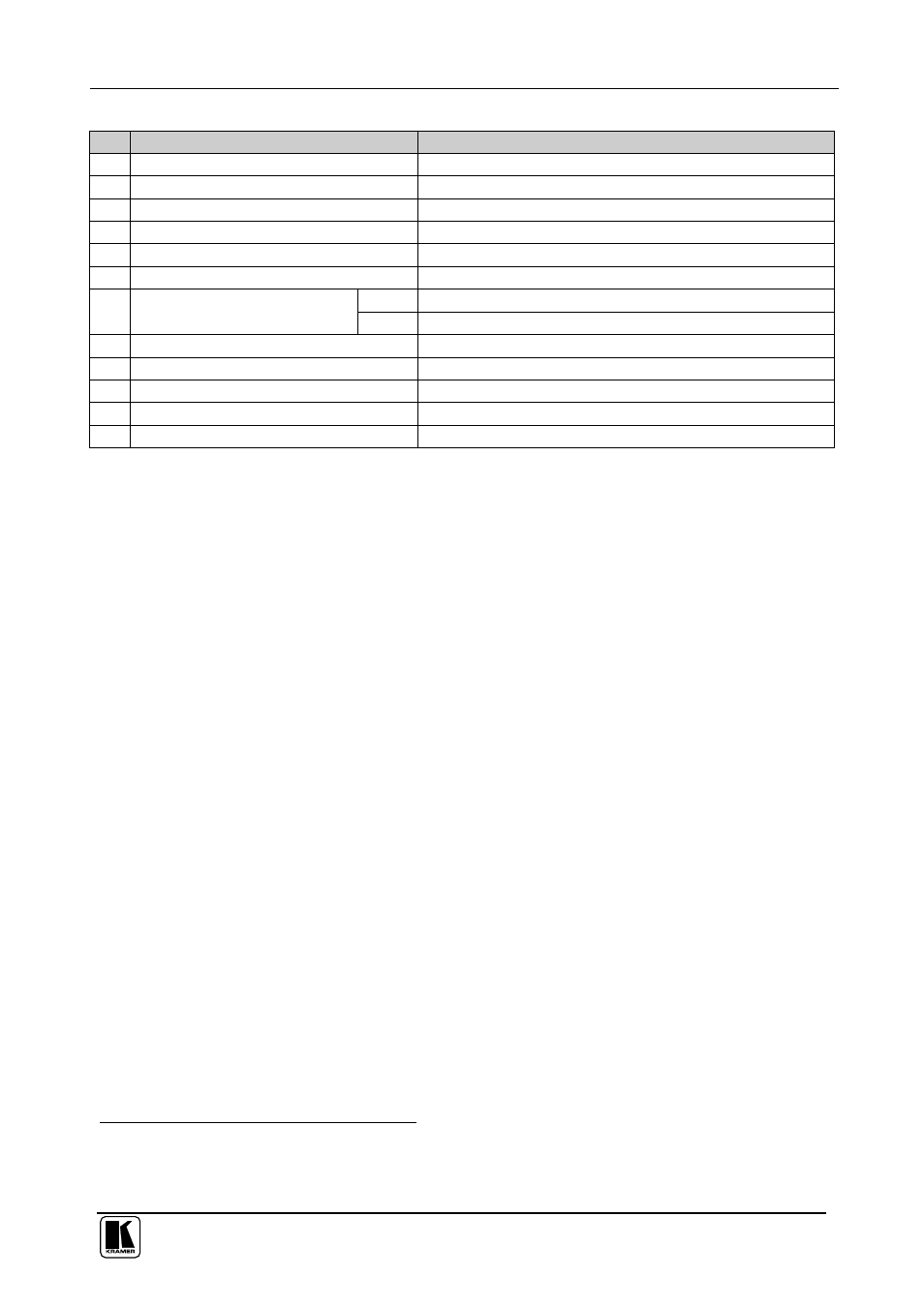
Table 1: VP-200AK 1:2 UXGA / Audio DA Features
#
Feature
Function
1
INPUT 3.5mm Mini plug Connector
Connects unbalanced audio to the audio source
2
LEFT LEVEL Trimmer
Adjusts the left audio signal level
3
OUT 1 3.5mm Mini plug Connector
Connects unbalanced stereo audio to the audio acceptor 1
4
RIGHT LEVEL Trimmer
Adjusts the right audio signal level
5
OUT 2 3.5mm Mini plug Connector
Connects unbalanced stereo audio to the audio acceptor 2
6
UXGA EQ. Trimmer
Adjusts the video EQ. (equalization) compensation
R2, L2 Connects balanced stereo audio to the audio acceptor 2
7
BALANCED AUDIO OUTPUT
Terminal Block Connectors
R1, L1 Connects balanced stereo audio to the audio acceptor 1
8
5V DC
+5V DC connector for powering the unit
9
INPUT 15-pin HD (F) Connector
Connect to the computer graphics source
10
OUTPUT 1 15-pin HD (F) Connector
Connect to the computer graphics acceptor 1
11
ON LED
Illuminates when receiving power
12
OUTPUT 2 15-pin HD (F) Connector
Connect to the computer graphics acceptor 2
5
Connecting the VP-200AK 1:2 UXGA / Audio DA
To connect your
VP-200AK 1:2 UXGA / Audio DA, as the example in
Figure 2 illustrates, do the following
1
:
1. Connect a computer graphics source to the 15-pin HD (F) INPUT
connector.
2. Connect
2
the 15-pin HD (F) OUTPUT connectors to up to two
acceptors, as follows:
Connect the OUTPUT 1 connector to acceptor 1 (for example, a
display)
Connect the OUTPUT 2 connector to acceptor 2 (for example, a
projector)
3. Connect the unbalanced audio source (for example, the computer graphics
source audio) to the INPUT 3.5mm mini jack connector.
4. Connect the unbalanced audio OUT 1 and OUT 2, 3.5mm mini jack
connectors, to up to two unbalanced audio acceptors (for example, tape
recorders).
5. Connect
2
the BALANCED AUDIO OUTPUT (R1, L1 and R2, L2)
terminal block connectors to up to two balanced audio acceptors (for
example, power amplifiers).
6. Connect the 5V DC power adapter to the power socket and connect the
adapter to the mains electricity (not shown in Figure 2).
1 Switch OFF the power on each device before connecting it to your VP-200AK. After powering up your VP-200AK, switch
on the power on each device
2 When only one output is required, use either of the outputs, and leave the other output unconnected