Kramer Electronics SD-7108 User Manual
Page 14
KRAMER ELECTRONICS LTD. 13
10.1 Operation of the SDI Distributors
⌦ Connect an SDI source to the BNC input socket of the 6104 or SD-7108 distributor.
⌦ Connect a Parallel digital video source to the DB25 input socket of the SD-7208.
⌦ Connect up to four (6104), or eight (SD-7108, SD-7208), SDI acceptors to the output sockets
of the distributor.
⌦ Connect, if required, a Parallel digital video acceptor to the PARALLEL OUT socket of the
SD-7108.
⌦ Adjust, only if required, the SDI output levels (SD-7108, SD-7208) using an insulated
screwdriver. Bear in mind the machines are factory pre-adjusted for 1:1 transparency, and
unnecessarily trimming the output level will upset this transparency.
10.2 Operation of the Digital Audio Distributors
For AES/EBU twisted pair connections (as defined by AES3-1992 standard) the SD-7816 DA should
be used. The signal is bi-phase coded, transformer coupled and transmitted in a balanced format on shielded
twisted pair wires. The signal level may be 2 to 7 volts peak to peak with a source impedance of 110 ohms.
The interconnecting cable should exhibit nominal 110 ohms characteristic impedance. When connecting the
source and the acceptors, special attention should be paid to the polarity of the connections.
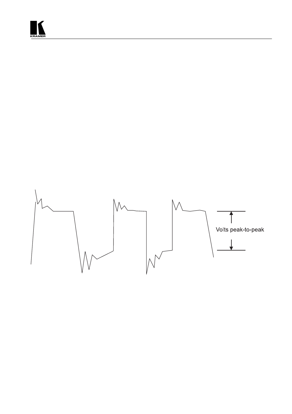
Measure the level of the input signal using an oscilloscope, (excluding overshoots and undershoots)
as shown in figure 8. Using this value, set the DIP-switches according to Table 6. (Table 6 is based on the
graph in figure 9 - “Professional format: 110 ohm, Balanced”).
Figure 8: Signal peak-to-peak measurement