Installation instructions, Prepare strike wiring a. electrolynx connectors – HES HT5000 User Manual
Page 3
Installation Instructions
3
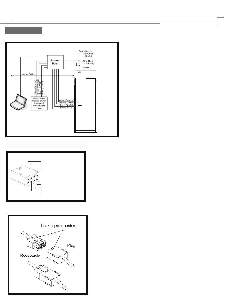
The HT5000 series drawing
below show the Hi
-
O application
.
Voltage: 12-24VDC
(11-28VDC range) operation
Filtered and Regulated Power Supply
Current: .
5 Amp Seated
.04 Amp Unseated
PIN 1 Black (0 VDC)
PIN 3 White (CANbus)
PIN 5
PIN 7 Brown (CANbus)
PIN 8
PIN 6
PIN 4
PIN 2 Red (+12 – 24 VDC)
-)]
NOTE:
For HT5000 (On the 8-Pin Connector):
PIN 2 Red (Power +12 - 24VDC)
PIN 1 Black [Power 0 VDC/Common(-)]
PIN 3 White CAN bus HIGH
PIN 7 Brown CAN bus LOW
endly with quick
cable lengths to a minimum.
.
The System is designed to be installation friendly with quick
connectors.
The total length of the bus should not be more then 50 meters
(164 feet) and stub (star) connections should not be more then
10 meters (33 feet). The optimal solution places the door
controller close to the door to keep cable lengths to a minimum.
IMPORTANT:
ElectroLynx connectors plug and lock together in only one way,
as shown.
Do NOT force connectors together.
Prepare Strike
Wiring
A. Electrolynx Connectors
B. Electrolynx Connector System Notes