Graymills Bed Filter OMI User Manual
Page 2
UNPACKING
Unpack and inspect unit carefully to verify that everything is
intact and there are no obstructions in the chain mechanism
or any other electrical or mechanical components. Do not run
power to system at this time.
SAFETY INSTRUCTIONS
Read this before using your product.
• Read and follow all safety instructions supplied with
chemical/coolant being used in your machine tool.
• To avoid damage to the unit, check power source for proper
voltage and phase. Unit comes standard with a transformer
capable of accepting either 230V or 460V, 3 phase power.
• As in all electrical circuits, it is highly recommended that an
electric safety device such as a fusible disconnect or circuit
breaker be installed in line before unit is connected.
• Do not use an extension cord to supply bed filter system.
• Check the rotation of the pump before starting operation.
Rotation should be in a clockwise direction looking down on
the motor (arrow on pump body indicates direction).
• Ensure that all fittings and connections are properly
tightened.
• It is important that sensitive electronic equipment, be kept a
safe distance from the Magnetic Separator, such as
• personal electronic devices such as pacemakers
• computers
• magnetic media such as credit cards
• Turn off power to the unit before beginning maintenance
on the Graymills Coolant Tank, Bed Filter, or Magnetic
Separator.
• Make sure that pump is spinning freely. See “Maintenance”
instructions.
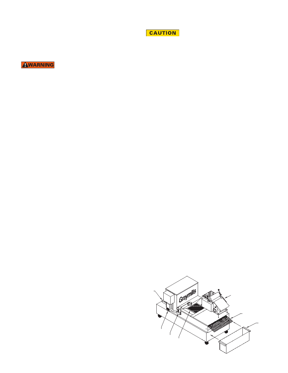
SYSTEM COMPONENTS
A Pump
Used to deliver the coolant in the tank to the machine.
B Gear Reducing Motor
Moves the filter media along as necessary.
C Liquid Level Control and Filtration
Float switch mechanism detects the level of coolant collected
in the filter valley. Switch operates the motor that moves the
filter media along when level is too high.
D Diffuser Tray
Collects larger particles before the coolant is deposited
on the filter media. Also helps spread deposits evenly,
increasing media life.
E Filter Media
Collects the particles to filter the coolant. Standard roll
is 150 yards, rated at 20 micron. Other micron ratings
available; contact Graymills for details.
F Sludge Box
Used to accumulate spent filter media and prevent run off to
floor.
G (Optional) Magnetic Separator
Removes ferrous material from coolant before fluid enters bed
filter or tank. Can be installed directly on bed filter for dual
stage separation, or run independently with pumping system.
UNIT SET UP
1 Verify operating voltage and make any necessary changes
to the connections to the transformer in the control box as
well as the pump. The unit is a dual voltage system and
the default setting should be 230V/3Ph. Follow the wiring
schematics on the transformer and pump to check/change
the power settings. Refer to Figures at bottom of page 3.
All electrical connections should conform to national/local
codes and be made by qualified personnel.
2 Position the unit in the area in which it will be operating.
3 Remove diffuser tray and lids from paper compartment and
chain area.
4 Fill the tank cavity with coolant until level is approximately
1 to 2 inches below side wall of tank, being careful not to
overfill.
5 Proceed to feed paper through the opening at the bottom of
the paper compartment and onto the chain until the chain
is completely covered. Extend filter media a few inches past
the chain. Position the sludge collection box at the end of the
tank and place end of filter paper over box so soiled media
drops into box.
6 Replace lids and reinstall diffuser tray.
7 Pump and bed filter may be wired separately in the event
there is a power feed from your machine tool to incorporate
the pump operation into the main control. If not, you may
run a water-tight conduit (customer supplied) from the pump
to the main control box and bring your main power feed
into it for a central connection. All electrical work must be
according to applicable codes.
8 Make the necessary connections as shown in the wiring
schematic, Figure 3. All electrical work must be according to
applicable codes.
9 Complete any other necessary installations to finish the hook
up. This includes attaching hoses and fittings (customer-
supplied) from the pump discharge to the machine tool. The
BFTS40 system has a 1/2” pump discharge; the BFTS80
and BFTS120 systems have a 3/4” pump discharge; the
BFTS160 system has a 1” pump discharge. Do not reduce
the outlet of the pump. Doing so will reduce the flow
capacity of the pump. Also plumb the return lines so they are
discharging directly onto the diffuser plate of the Bed Filter
or intake of the Magnetic Separator.
795-92645 03-13 Bed Filter/Magnetic Separator OMI
A
B
C
D
G
E
F
Figure 1