Installation – Graymills DDP .5' Pump User Manual
Page 5
5
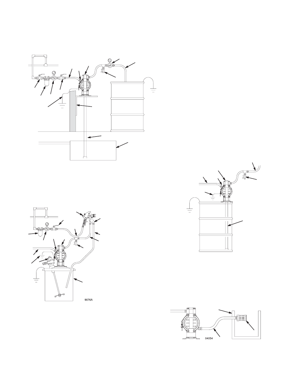
Installation
The typical Installations in Figure 1 are only guides for selecting and installing system components. Contact Graymills or
your distributor for assistance in planning a system to suit your needs.
KEY
A
Pump
C
Electrically conductive air supply line
D
Air line quick disconnect
H
Fluid drain valve (required)
K
Electrically conductive fluid supply hose
L
Fluid suction line
Y
Ground wire (required; see page 6
for installation instructions)
9074A
Figure 1
H
J
ABOVE-GROUND TRANSFER INSTALLATION
A
C
D
K
L
M
N
Y
E
9075A
H
55-GALLON BUNG PUMP INSTALLATION
A
C
D
K
L
Y
AIR SPRAY INSTALLATION
A
E
K
P
R
S
T
U
V
Y
H
C
D
KEY
A
Pump
B
Bleed-type master air valve
(required for pump)
C
Electrically conductive
air supply line
D
Air line quick disconnect
E
Master air valve (for accessories)
F
Air line filter
G
Pump air regulator
H
Fluid drain valve (required)
J
Fluid regulator (optional)
K
Electrically conductive
fluid supply hose
L
Fluid suction line
M
Underground storage tank
N
Wall mounting bracket
Y
Ground wire (required; see page 6
for installation instructions)
KEY
A
Pump
C
Electrically conductive air line to pump
E
Gun air line shutoff valve
F
Air line filter
G
Gun air regulator
H
Fluid drain valve (required)
K
Electrically conductive fluid supply hose
P
Circulating valve
R
Electrically conductive air line to gun
S
Air spray gun
T
Electrically conductive fluid return line
U
5-gallon pail
V
Agitator
Y
Ground wire (required; see page 6
for installation instructions)
F
G
B
F
All wetted and non-wetted pump parts must be
compatible with the fluid being pumped.
KEY
W Muffler
X
Electrically Conductive Air Exhaust Hose
Z
Container for Remote Air Exhaust
W
X
Z
VENTING EXHAUST AIR
G