Festo Регуляторы давления LRS User Manual
Lfr-/lr-/lf-…-d-…-micro
Warnung, Warning, Varning
. . . . . . . . . . . . . . . . . . . . . . . . . .
de Unter Druckluft stehende Produkte können
Personen- oder Sachschäden verursachen.
• Schalten Sie vor Installations- und
Wartungsarbeiten die Druckluftversorgung aus.
• Verwenden Sie zur Entlüftung der Anlage
Absperrventile in der Druckluftzuleitung.
en Products under pressure can cause injury to
human beings and damage to property.
• Before carrying out installation and maintenance
work always switch off the compressed air
supply.
• Use shut-off valves in the compressed air tubing
for exhausting the system.
sv Produkter med tryckluft kan orsaka personskador
eller materiella skador.
• Koppla från tryckluftsmatningen innan
installations- och underhållsarbeten påbörjas.
• Använd avstängningsventiler i
tryckluftsmatarledningen för att avlufta
anläggningen.
Hinweis, Note, Information
. . . . . . . . . . . . . . . . . . . . . . . . . . .
de Einbau und Inbetriebnahme nur von autorisiertem
Fachpersonal, gemäß Bedienungsanleitung.
Dieses Produkt ist ausschließlich zur Verwendung
mit Druckluft vorgesehen. Zur Verwendung mit
anderen Medien (Flüssigkeiten oder Gasen) ist das
Produkt nicht geeignet.
en Fitting and commissioning to be carried out only by
qualified personnel in accordance with the
operating instructions.
This product is designed to be operated with
compressed air only. The product is not suitable for
use with other media (liquids or gases).
sv Montering och idrifttagning får endast utföras av
behörig personal enligt bruksanvisningen.
Denna produkt är endast avsedd för användning
med tryckluft. Produkten är inte avsedd för
användning med andra medier (vätskor eller
gaser).
7
6
2 Nm
1
2
3
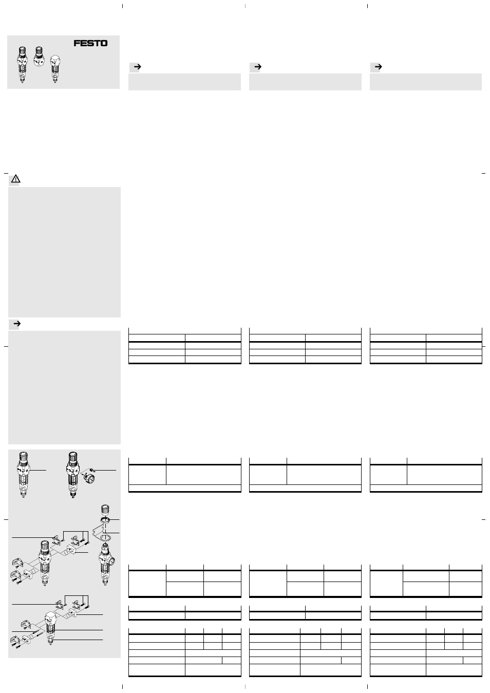
Bild 1 / Fig. 1
Bild 2 / Fig. 2
Bild 3 / Fig. 3
Bild 4 / Fig. 4
0,5 Nm
5
8
9
0,85 Nm
max. 1,3 Nm
Bild 5 / Fig. 5
3
4
5
0,2 Nm
0,5 Nm
Filterregelventil LFR,
de
. . . . . . . . . . . . . . . . . . . . . . . . . . . . . . . . . . . . . . . . .
Druckregelventil LR, Filter LF
1 Anwendung
Bestimmungsgemäß regelt das LFR/LR Druckluft im nachfolgenden
Strang auf den eingestellten Ausgangsdruck p2. Dabei glättet das
LFR/LR Druckschwankungen. Der Ausgangsdruck p2 ist innerhalb des
Druckregelbereichs (
“Technische Daten”) einstellbar.
Das LFR/LF mit Wasserabscheider befreit die Druckluft von Schmutz-
partikeln und Kondenswasser.
2 Voraussetzungen für den Produkteinsatz
Hinweis
. . . . . . . . . . . . . . . . . . . . . . . . . . . . . . . . . . . . . . . . . . . . . . . . . .
Durch unsachgemäße Handhabung entstehen Fehlfunktionen.
Stellen Sie sicher, dass die nachfolgenden Vorgaben stets
eingehalten werden.
• Vergleichen Sie die Grenzwerte in dieser Bedienungsanleitung
mit denen Ihres Einsatzfalls (z.B. Betriebsmedium, Drücke,
Temperaturen, Massen, Durchflüsse).
• Berücksichtigen Sie die Umgebungsbedingungen am Einsatzort.
• Verwenden Sie das Produkt im Originalzustand ohne jegliche
eigenmächtige Veränderung.
• Entfernen Sie Partikel in den Zuleitungen mittels Durchblasen der
Rohre und Schläuche. Dadurch schützen Sie das Gerät vor frühzeiti-
gem Ausfall oder höherem Verschleiß (
DIN ISO 4414, Abs. 9.4).
3 Einbau
3.1 Mechanisch
Berücksichtigen Sie beim Einbau folgende Punkte:
• Beachten Sie die Durchflussrichtung von 1 nach 2.
Als Orientierung dient der Pfeil
1 auf dem Produktgehäuse
(
Bild 1).
• Plazieren Sie das LFR/LF mit ausreichend Platz unterhalb der
Filterschale (min. 60 mm).
• Justieren Sie das LFR/LF senkrecht stehend (
_5°).
Manometermontage (
Bild 2)
1. Bei LFR/LR-…-O:
• Entfernen Sie die Verschlussschraube
2 am Manometeran-
schluss oder am Alternativanschluss auf der Geräterückseite.
Bei LFR/LR mit Manometer im Lieferumfang:
• Setzen Sie die Verschlussschraube um, falls Sie den Alternativ-
anschluss auf der Geräterückseite für das Manometer verwenden
wollen.
2. Drehen Sie das Manometer MA im Uhrzeigersinn bis zum Anschlag
in das LFR/LR. Die Manometerdichtung ist auf dem Gewinde-
anschlusszapfen vormontiert.
Wandmontage (LFR/LR
Bild 3 oder 4, LF
Bild 5)
• Befestigen Sie ggf. die Anschlussplatten
3.
Nur LF: Drücken Sie vorab die Stehbolzen
4 in die Durchgangs-
bohrungen des LF.
Mit Befestigungswinkel HFOE
5:
1. Nur LF ohne Anschlussplatten: Drücken Sie den Stehbolzen
4 in
die Durchgangsbohrung des LF, die der Wand am nächsten ist.
2. Befestigen Sie den HFOE
5 mit je einer Schraube am Gerät.
Mit Befestigungswinkel HRS
6:
1. Befestigen Sie den HRS
6 mit Hilfe zweier Schrauben an der
vorgesehenen Stelle.
2. Ziehen Sie den Drehknopf vom Drehbolzen nach oben weg.
3. Schieben Sie den Reglerkopf durch die Ringbohrung.
4. Drehen Sie die Sechskantmutter
7 fest.
5. Drücken Sie den Drehknopf auf den Drehbolzen bis er hörbar
einrastet.
3.2 Pneumatisch
Bei Verwendung von Anschlussverschraubungen:
• Beachten Sie die Einschraubtiefe der Anschlussgewinde.
Max. Einschraubtiefe
ISO 228
NPT
LFR/LR/LF-M5:
5 mm
–
LFR/LR/LF-M7:
6 mm
–
LFR/LR/LF-
x:
8 mm
LFR/LR/LF-N
x: 7 mm
• Drehen Sie die Verschraubungen in die pneumatischen Anschlüsse
unter Verwendung von geeignetem Dichtmaterial.
4 Inbetriebnahme
Zur Einstellung des LFR/LR:
1. Entriegeln Sie den Drehknopf in dem Sie den Drehknopf nach oben
ziehen (vom Gehäuse weg).
2. Drehen Sie den Drehknopf in Richtung “–” ganz zu.
3. Belüften Sie Ihre Anlage langsam.
4. Drehen Sie den Drehknopf in Richtung “+” bis der gewünschte
Druck am Manometer angezeigt wird.
Der zulässige Druckregelbereich (
“Technische Daten”) darf
dabei nicht überschritten werden.
Richtig beaufschlagt, liegt der Eingangsdruck p1 um mindestens
0,5 bar höher als der Ausgangsdruck p2.
5. Verriegeln Sie den Drehknopf.
5 Wartung und Pflege
Bei Erreichen eines Kondensatpegels von ca. 10 mm unterhalb des
Filterelements:
Manueller Ablass
Halbautomatischer Ablass LFR/LF-…-H
Ablass-Schraube
(von unten gesehen)
gegen den Uhrzeiger-
sinn aufdrehen.
– Gerät kurzzeitig entlüften (p1 = 0 bar)
oder
– Ablass-Schraube (von unten gesehen)
gegen den Uhrzeigersinn aufdrehen.
Dadurch fließt das Kondensat ab.
Wechsel der Filterpatrone (nur LFR/LF)
• Wechseln Sie die Filterpatrone bei geringem Durchfluss trotz
unveränderter Druckeinstellung:
1. Entlüften Sie das Gerät.
2. Filterschale
9 und Filterteller 8 gegen den Uhrzeigersinn drehen
(neue Filterpatrone nur am unteren Ende greifen).
3. Einzelteile in umgekehrter Reihenfolge montieren.
4. Wiederinbetriebnahme gemäß Kapitel 4 “Inbetriebnahme”.
Reinigung
• Reinigen Sie bei Bedarf das Gerät mit einem weichen Lappen von
außen.
Zulässige Reinigungsmedien sind Seifenlauge (max. +60 °C) oder
Waschbenzin (aromatenfrei).
6 Störungsbeseitigung
Störung
Mögliche Ursache
Abhilfe
Geringer Durchfluss
(bei Luftverbrauch
b i ht d
B t i b
Filterpatrone ist
verschmutzt
Filterpatrone
auswechseln
(
bricht der Betriebs-
druck zusammen)
Verengung zwischen
Absperrventil und
Wartungseinheit
Leitung kontrollieren
7 Zubehör
Bezeichnung
Typ
Filterpatrone
LFP-D-MICRO-5M
8 Technische Daten
Typ
LFR
LF
LR
Eingangsdruck
[bar]
1 … 10
0 … 10
1 … 10
Druckregelbereich
[bar]
0,5 … 7
–
0,5 … 7
Betriebsmedium
Druckluft
Einbaulage
senkrecht
_5°
beliebig
Umgebungstemperatur
Mediumstemperatur
[°C]
[°C]
-10 … +60
-10 … +60
Filter regulator LFR,
en
. . . . . . . . . . . . . . . . . . . . . . . . . . . . . . . . . . . . . . . . . .
pressure regulator LR, filter LF
1 Application
The LFR/LR pressure regulator has been designed to regulate
compressed air in the following string to the set output pressure p2.
The LFR/LR smooths out fluctuations in pressure here. The output
pressure p2 can be set within the pressure regulating range
(
“Technical specifications”). The LFR/LF with water separator frees
the compressed air from dirt particles and condensation water.
2 Safety conditions
Note
. . . . . . . . . . . . . . . . . . . . . . . . . . . . . . . . . . . . . . . . . . . . . . . . . . . . . .
Improper handling can result in malfunctions.
Make sure that the following specifications are always observed.
• Compare the maximum values specified in these operating
instructions with your actual application (e.g. operating media,
pressures, forces, temperatures, masses, flow rates).
• Take into consideration the ambient conditions at the location of
use.
• Unauthorized product modification is not permitted.
• Remove dirt particles in the supply lines by blowing out the tubing
with compressed air. In this way you will protect the device from
premature failure or heavy wear (
DIN ISO 4414, section 9.4).
3 Installation
3.1 Mechanical installation
Consider the following points:
• Note the direction of flow from 1 to 2.
The arrow
1 on the product housing serves as an orientation
(
Fig. 1).
• Place the LFR/LF with sufficient space below the filter bowl
(min. 60 mm).
• Adjust the LFR/LF when it is standing vertically (
_5°).
Fitting the pressure gauge (
Fig. 2)
1. With LFR/LR-…-O:
• Remove the screw plug
2 on the pressure gauge connection or
alternatively on the connection on the rear of the device.
With LFR/LR supplied with pressure gauge
• Place the screw plug on the other connection if you wish to use
the alternative connection on the rear of the device for the
pressure gauge.
2. Screw the pressure gauge MA in a clockwise direction as far as
possible into the LFR/LR. The pressure gauge seal is pre-fitted on
the threaded connecting trunnion.
Fitting onto a wall (LFR/LR
Fig. 3 or 4, LF
Fig. 5)
• If applicable fasten the sub-bases
3.
Only LF: First press the spacer bolts
4 into the through holes
of the LF.
With fastening bracket HFOE
5:
1. Only LF without sub-bases: Press the spacer bolts
4 into the
through hole of the LF nearest to the wall.
2. Fasten the HFOE
5 to the device with a screw.
With fastening bracket HRS
6:
1. Fasten the HRS
6 in the intended position with two screws.
2. Pull the rotary knob upwards away from the pintail.
3. Push the controller head through the ring bore.
4. Tighten the hexagon nut
7.
5. Press the rotary knob on the pintail until you hear it latch into
position.
3.2 Pneumatic installation
If using screw connectors:
• Note the screw-in depth of the connector threads.
Max. screw-in depth
ISO 228
NPT
LFR/LR/LF-M5:
5 mm
–
LFR/LR/LF-M7:
6 mm
–
LFR/LR/LF-
x:
8 mm
LFR/LR/LF-N
x: 7 mm
• Screw the connectors into the pneumatic connections using a
suitable sealing material.
4 Commissioning
Setting the LFR/LR:
1. Unlock the rotary knob by pulling the knob upwards (away from the
housing).
2. Turn the rotary knob as far as possible in the direction “–”.
3. Pressurize your system slowly.
4. Turn the rotary knob in the direction “+” until the desired pressure
is shown on the pressure gauge.
The permitted pressure regulating range (
“Technical
specifications”) must not be exceeded.
If pressurized correctly, the input pressure p1 will be at least
0.5 bar higher than the output pressure p2.
5. Lock the rotary knob.
5 Care and maintenance
When there is a condensate level of approx. 10 mm below the filter
element.
Manual outlet
Semi-automatic outlet LFR/LF-…-H
Unscrew the outlet
screw in an anti-
clockwise direction
(as seen from below).
– Briefly exhaust the device (p1 = 0 bar)
or
– Unscrew the outlet screw in an anti-clock-
wise direction (as seen from below).
The condensate will then flow out.
Replacing the filter cartridge (only LFR/LF)
• Replace the filter cartridge if the flow is only slight in spite of
unmodified pressure setting:
1. Exhaust the device.
2. Turn the filter bowl
9 and the filter plate 8 in an anti-clockwise
direction (grasp the new filter cartridge at the lower end).
3. Refit the components in the reverse order.
4. Carry out commissioning again in accordance with chapter 4
“Commissioning”.
Cleaning
• If the device is dirty, clean the exterior with a soft cloth.
Permitted cleaning agents are soap suds (max. +60 °C) or
petroleum ether (free of aromatic compounds).
6 Troubleshooting
Fault
Possible cause
Remedy
Slight flow
(operating pressure
b
k d
h
Filter cartridge is
dirty
Replace filter
cartridge
( p
g p
breaks down when
air is consumed)
Restriction between
shut-off valve and
service unit
Check the tubing
7 Accessories
Description
Type
Filter cartridge
LFP-D-MICRO-5M
8 Technical specifications
Type
LFR
LF
LR
Input pressure
[bar]
1 … 10
0 … 10
1 … 10
Pressure regul. range
[bar]
0.5 … 7
–
0.5 … 7
Operating medium
compressed air
Installation position
vertical
_5°
as desired
Ambient temperature
Medium temperature
[°C]
[°C]
-10 … +60
-10 … +60
Filterregulator LFR,
sv
. . . . . . . . . . . . . . . . . . . . . . . . . . . . . . . . . . . . . . . . . . .
tryckregulator LR, filter LF
1 Användning
LFR/LR reglerar tryckluft i efterföljande slinga till inställt utgångs-
tryck p2. Därvid utjämnar LFR/LR tryckvariationer. Utgångstryck p2
kan ställas in inom tryckregleringsområdet (
“Tekniska data”).
LFR/LF med vattenavskiljare renar tryckluften från smutspartiklar och
kondensvatten.
2 Förutsättningar för korrekt användning av produkten
Information
. . . . . . . . . . . . . . . . . . . . . . . . . . . . . . . . . . . . . . . . . . . . .
Felaktigt handhavande kan leda till felfunktioner.
Se till att nedanstående anvisningar alltid följs.
• Jämför gränsvärdena i denna bruksanvisning med din aktuella
applikation (t.ex. driftmedium, tryck, temperatur, massa och flöde).
• Ta hänsyn till rådande driftmiljö.
• Använd produkten i originalskick utan några som helst egna
förändringar.
• Avlägsna främmande partiklar i matarledningarna genom att blåsa
igenom rör och slangar. På så sätt undviker du att enheten slutar
fungera i förtid eller utsätts för ökat slitage (
DIN ISO 4414,
avsnitt 9.4).
3 Montering
3.1 Mekaniska komponenter
Observera följande punkter vid montering:
• Beakta flödesriktningen från 1 till 2.
Pilen
1 på produkthuset fungerar som hjälp (
Bild 1).
• Placera LFR/LF så att det finns tillräckligt med plats under
filterskålen (min. 60 mm).
• Se till att LFR/LF står lodrätt (
_5°).
Manometermontering (
Bild 2)
1. Vid LFR/LR-…-O:
• Lossa blindpluggen
2 på manometeranslutningen eller på den
alternativa anslutningen på regulatorns baksida.
Vid LFR/LR med manometer som ingår i leveransen:
• Flytta blindpluggen om du vill använda den alternativa
anslutningen på regulatorns baksida för manometern.
2. Vrid manometer MA medurs till anslaget i LFR/LR.
Manometertätningen har redan monterats på gängtappen.
Väggmontering (LFR/LR
Bild 3 eller 4, LF
Bild 5)
• Fixera vid behov anslutningsplattorna
3.
Endast LF: Tryck först pinnbultarna
4 i de genomgående hålen
på LF.
Med fästvinkeln HFOE
5:
1. Endast LF utan anslutningsplattor: Tryck pinnbulten
4 i det
genomgående hålet på LF som är närmast väggen.
2. Fixera HFOE
5 med vardera en skruv på regulatorn.
Med fästvinkeln HRS
6:
1. Fixera HRS
6 med två skruvar på avsett ställe.
2. Dra regulatorratten uppåt från vridbulten.
3. Skjut regulatorhuvudet genom ringhålet.
4. Dra åt den räfflade sexkantsmuttern
7.
5. Tryck regulatorratten på vridbulten tills ratten hakar fast.
3.2 Pneumatiska komponenter
Vid användning av instickskopplingar:
• Beakta inskruvningsdjupet för anslutningsgängan.
Max. inskruvningsdjup
ISO 228
NPT
LFR/LR/LF-M5:
5 mm
–
LFR/LR/LF-M7:
6 mm
–
LFR/LR/LF-
x:
8 mm
LFR/LR/LF-N
x: 7 mm
• Skruva in instickskopplingarna i de pneumatiska anslutningarna
och använd lämpligt tätningsmaterial.
4 Idrifttagning
Inställning av LFR/LR:
1. Lossa regulatorratten genom att dra ratten uppåt (från huset).
2. Stäng regulatorn genom att vrida ratten så långt det går åt
riktningen “–”.
3. Pålufta anläggningen långsamt.
4. Vrid regulatorratten mot “+” tills önskat tryck visas på manometern.
Tillåtet tryckregleringsområde (
“Tekniska data”) får inte
överskridas.
Korrekt trycksatt är ingångstrycket p1 minst 0,5 bar högre än
utgångstrycket p2.
5. Lås regulatorratten.
5 Underhåll och skötsel
När kondensatnivån är ca. 10 mm under filterelementet:
Manuell avtappning
Halvautomatisk avtappning LFR/LF-…-H
Öppna avtappnings-
skruven moturs
(sett nedifrån).
– Avlufta enheten kortvarigt (p1 = 0 bar)
eller
– Öppna avtappningsskruven moturs
(sett nedifrån).
Kondensatet tappas av.
Byte av filterpatron (endast LFR/LF)
• Byt ut filterpatronen vid låg genomströmning trots oförändrad
tryckinställning:
1. Avlufta enheten.
2. Vrid filterskålen
9 och filterplattan 8 moturs (ta endast i den
nedre änden av den nya filterpatronen).
3. Montera de enskilda delarna i omvänd ordningsföljd.
4. Idrifttagning på nytt enligt kapitlet 4 “Idrifttagning”.
Rengöring
• Rengör vid behov utsidan med en mjuk trasa.
Tillåtna rengöringsmedel är tvållösning (max. +60 °C) eller
tvättbensin (aromatfri).
6 Åtgärdande av fel
Fel
Möjlig orsak
Åtgärd
Låg genomström-
ning (inget
d iftt
k id
Filterpatronen är smutsig
Byt ut
filterpatronen
g ( g
drifttryck vid
luftförbrukning)
Trångt utrymme mellan
avstängningsventilen och
serviceenheten
Kontrollera
ledningen
7 Tillbehör
Beteckning
Typ
Filterpatron
LFP-D-MICRO-5M
8 Tekniska data
Typ
LFR
LF
LR
Ingångstryck
[bar]
1 … 10
0 … 10
1 … 10
Tryckregleringsområde
[bar]
0,5 … 7
–
0,5 … 7
Driftmedium
tryckluft
Monteringsläge
Lodrätt
_5°
valfritt
Omgivningstemperatur
Medietemperatur
[°C]
[°C]
-10 … +60
-10 … +60
LFR-/LR-/LF-…-D-…-MICRO
Bedienungsanleitung
Operating instructions
Bruksanvisning
Original: de
Festo AG & Co. KG
Postfach
D-73726 Esslingen
Phone:
+49/711/347-0
www.festo.com
0809b
658 312