RMS Technologies R208 DRIVER User Manual
Page 12
RMS Technologies
Page 12
Version 1.22
R208 Microstepping Driver Manual
8/31/2007
7. CONFIGURING AND CONTROLLING THE R208
Signal Control Specifications
Default Settings
Current
1.4 Amp
Step Resolution
8x microstep
Direction of rotation
Counterclockwise
Current Cutback
Switch
Enabled
Read step pulse from
Falling Edge (-)
Table 3: Default Settings
The R208 is set to these default
settings when Pins 2, 3, 4, and 5
are left open and untouched.
Step Resolution
SR1
(Black)
SR2
(Brown)
Full
Close
Close
Half
Close
Open
1/4
Open
Close
1/8
Open
Open
Table 4: Step Resolution Settings
SR1 (Pin 2) and SR2 (Pin 3) are used
to preset the step resolution by
selective contact closure to ground
(Pin 7).
WARNING: Do not change the Step Resolution on the fly, loss of step will
occur.
Enable/Disable
Enable
Open
Disable
Close
Table 5
Disable the Driver by closing the connection
between Pin 4 and Signal Ground.
Direction
Clockwise
Close
Counterclockwise
Open
Table 6
Change direction of rotation by closing the
connections between Pin 5 and the Signal
Ground.
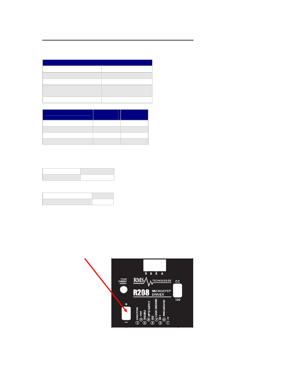
Step Pulse Input Read Selection
The R208 RoHS version now has the option to change the way the R208 reads in the step
pulse train. By default, it understands one pulse when it reads the falling edge of the pulse.
To change this setting so that it reads one pulse when it sees a rising edge of the pulse,
simply turn power off, switch the dipswitch towards the “+” (positive) silkscreen marker,
then power back on.
Note: Old units read the pulse on the falling edge (-).