Comfort-Aire IR60S User Manual
Page 3
ELECTRICAL INSTALLATION
WARNING: To assure safe operation, installa-
tion must be done by a certified electrician and
must adhere to local, state and national electrical
codes.
Use a certified ground fault protection device for
wet environment installations.
1. Supply voltage must correspond to the voltage
indicated on unit’s rating plate.
2. The cord from each terminal box must be hard
wired and properly grounded.
WARNING: Each power supply circuit must be
provided with a means of disconnection, and the
disconnecting means must be grouped.
WALL-MOUNTED INSTALLATION
WARNING: Observe minimum clearances shown
in chart above.
1. Securely fasten the L-shaped brackets to the
mounting surface using both of the fixing holes in
the short part of the bracket. NOTE: Wall bolts are
not supplied: select an appropriate size to provide
adequate support for the weight of the unit and
taking into consideration any wind load conditions.
CAUTION: If there is any question about security
of bolts and fixings, contact a professional con-
tractor.
2. Mount the heater to the brackets with the terminal
box at the bottom of the heater.
3. Adjust the heater to the desired directional angle,
then fix in this position by tightening the fixing
bolts on the brackets at the rear of the heater.
CAUTION: Do not position the heater at an angle
greater than 50° or less than 30°.
INTRODUCTION
Heat Controller’s infrared heater produces radiant heat that warms people and objects
rather than the air surrounding them. The heater can be mounted on a wall or ceiling,
and adjustable brackets allow the heat to be directed where desired.
This heater is designed for outdoor commercial use only.
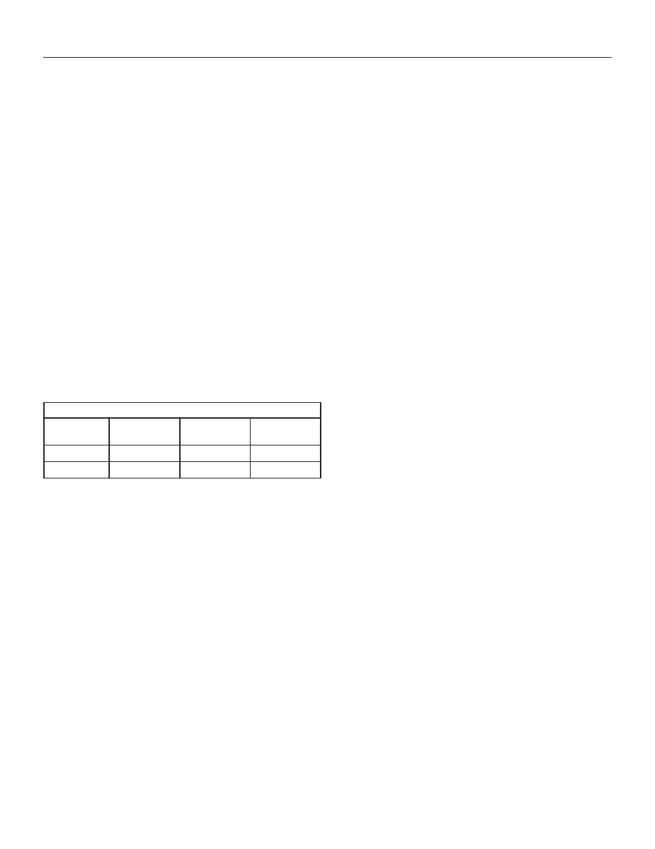
MINIMUM CLEARANCE DISTANCES FROM...
MODEL
FLOOR
CEILING
ADJACENT
WALLS
IR30S
8' (2.44 m)
1' 8" (.51 m)
36" (.91 m)
IR60S
10' (3.05 m) 1' 8" (.51 m) 48" (1.22 m)
Installation & Operation
Radiant Infrared Heater
Heat Controller
4. Secure the electrical supply cable so it does not
come in contact with the heater body or obstruct the
air vents. Follow local and national electrical code
requirements.
CEILING-MOUNTED INSTALLATION
WARNING: Observe minimum clearances shown
in chart at left.
1. Heater should be hung using non-flexible mount-
ing brackets (not supplied). Select brackets that
will maintain a minimum clearance of 1' 8" (.51 m)
from the ceiling.
2. Bolts and fixings (not supplied) should be of an ap-
propriate size to provide adequate support for the
weight of the unit and any additional load resulting
from wind conditions.
CAUTION: If there is any question about security
of bolts and fixings, contact a professional con-
tractor.
3. Secure the heater to the mounting brackets with
the heater facing directly down.
4. Secure the electrical supply cable so it does not
come in contact with the heater body or obstruct
the air vents. Follow local NEC code require-
ments.
ADJUSTING DIRECTIONAL POSITIONING
WARNING! Never attempt to move heater while it
is operating. Personal injury could result.
1. Power to the heater from the main supply must be
OFF to adjust the position. (Turn off circuit breaker.)
2. Allow the heater to cool before re-positioning the
angle.
3. Loosen the fixing bolts on the brackets at the rear
of the heater; re-position heater as desired, then
re-tighten the fixing bolts.
CAUTION: Do not position the heater at an angle
greater than 50° or less than 30°.
3