Component locations for condensing type furnaces – Comfort-Aire GDD95A Downflow Furnaces User Manual
Page 7
7
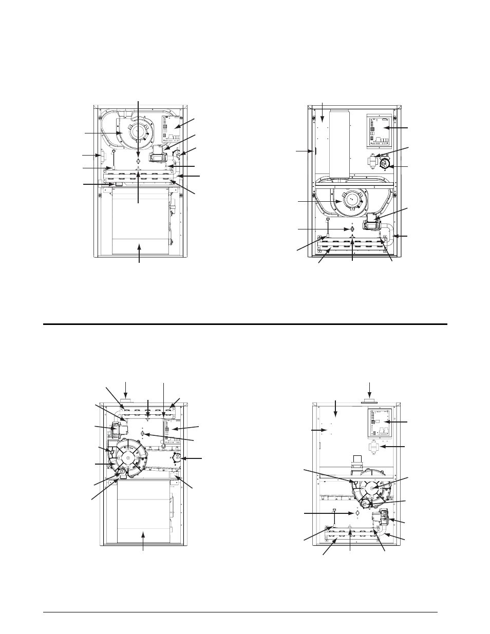
COMPONENT LOCATIONS FOR NON-CONDENSING TYPE FURNACES
Blower
Door
Switch
Burner
Assembly
Flame Sensor
Gas
Manifold
Gas Valve
Igniter
Inducer
Assembly
Pressure
Switch
Roll-Out
Switch
Transformer
Blower
Assembly
Furnace
Control
Board
Main Air
Limit Switch
Comb
ustion
Tube
Gas
Manifold
Gas Valve
Inducer
Assembly
Pressure
Switch
Transformer
Blower Assembly
(behind blower panel)
Burner
Assembly
Flame
Sensor
Roll-Out
Switch
Igniter
Main Air
Limit Switch
Blower
Door Switch
(behind blower panel)
GUH80A
Upflow / Horizontal Gas Furnace
GDD80A
Downflow Gas Furnace
Furnace
Control
Board
Single Stage Models
Blower
Assembly
Blower Door
Switch
Burner
Assembly
Furnace
Control
Board
Finish
Flange
Flame
Sensor
Gas
Manifold
Gas
Valve
Igniter
Inducer
Assembly
Main Air
Limit Switch
Inducer
Pressure Switch
Condensate
Pressure Switch
(‘B’, ‘C’, & ‘D’ cabinets only)
Roll-Out
Switch
Transformer
Inducer
Limit Switch
Finish
Flange
Blower Door
Switch
(behind blower panel)
Burner
Assembly
Flame
Sensor
Gas Manifold
Gas Valve
Igniter
Inducer
Assembly
Inducer
Pressure
Switch
Vent Limit
Switch
Furnace
Control
Board
Main Air
Limit Switch
Transformer
Roll-Out
Switch
GUH92A
Upflow / Horizontal Gas Furnace
GDD92A
Downflow Gas Furnace
Blower Assembly
(behind blower panel)
COMPONENT LOCATIONS FOR CONDENSING TYPE FURNACES
Single Stage Models