Indoor unit installation – Comfort-Aire DVH 24 User Manual
Page 7
7
Heat Controller
DVC/DVH Inverter Mini-Split
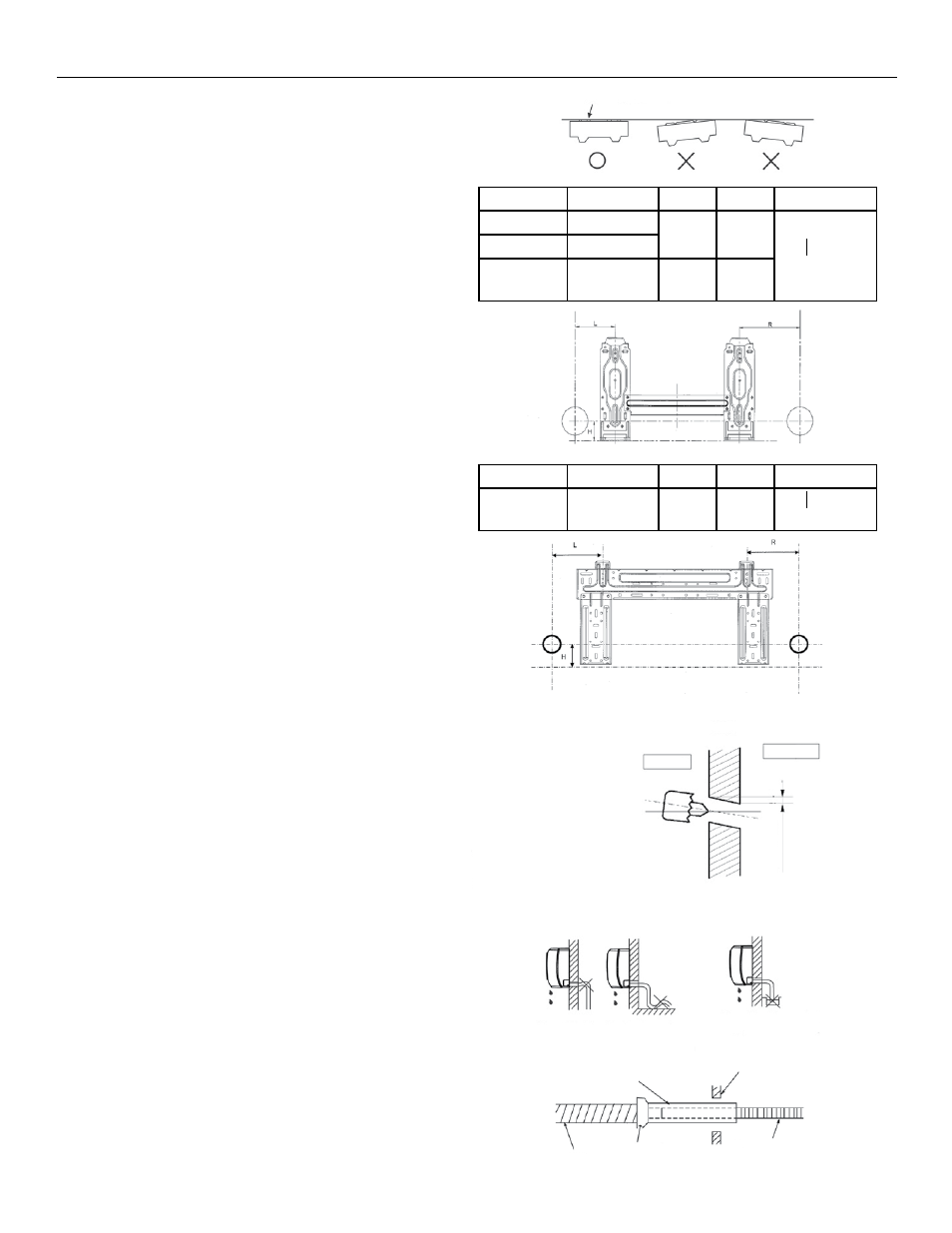
Model
R
L
H
Hole Diameter
DVC/DVH24
(6.4in)
163mm
(11.5in)
293mm
(1.8in)
45mm
02.56 in
(65mm)
Fig. 8
Indoor unit installation
1. Wall Bracket Mounting
A. There are two tabs on the back of the
indoor unit that hold the wall bracket onto
the unit. Press them down with a flat head
screwdriver to release the wall bracket from
the back of the unit.
B. Mount the wall bracket flush on structural parts
(studs) of the wall with proper unit clearances
in consideration. (Fig. 1 and Fig. 9)
NOTE: Any space between the unit and the
wall may cause noise or vibration.
C. Screw the wall bracket onto the wall with
type “A” self-tapping screws. If the wall
is made of brick, concrete or the like, drill
1/4” (5mm) diameter pilot holes in the wall.
Use anchors in conjunction with mounting
screws.
NOTE:
• Drill holes in the wall according to the stud
locations and corresponding mounting points
on the actual wall bracket that comes with your
unit. Wall brackets may vary by model and
specifications are subject to change.
• It is important to use all screws provided to
seure the wall bracket to the wall.
2. Create Opening for refrigerant and
condensate lines
A. Determine hole position according to the
wall bracket that comes with your unit, the
unit’s required clearances (Fig. 1) and which
direction (left/right) the lines will be routed
from the back of your unit (Fig. 14). Drill
2.5”(65mm) hole angled downward (approx.
45°) toward the outdoors. (Fig. 11).
NOTE: Ensure that neither studs nor plumbing
are located directly behine the propsed hole
location.
B. Always use a conduit to route the piping
though the hole in the wall. Properly seal
the hole after routing the pipes through to
prevent debris, insects, or small animals
from entering.
3. Condensate Drainage
A. Run the drain hose sloping downward. Do not
install the drain hose as illustrated in Fig.12.
B. When extending the drain hose, with locally
purchased hose, insulate the connection
with armaflex or similar pipe insulation
material. (Fig. 13)
Fig. 10
Fig. 9
Wall Bracket should be
flush with the interior wall
Fig. 12
Fig. 11
45°
Model
R
L
H
Hole Diameter
DVC/DVH09
(3.6in) 92
(6.7in)
170mm
(1.8in)
45mm
02.56 in
(65mm)
DVC/DVH12 (3.7in) 95mm
DVC/DVH18 (3.1in) 80mm (3.9in)
100mm
(1.8in)
45mm
Fig. 13
Indoor
Outdoor
Wall
Wall Cap
Extension drain-
hose
Wall
Drain hose
Pipe Insulation
Do not block water flow by a rise
Do not put the end of
drain hose into water