Operation australian monitor rmm51 impedance meter – Australian Monitor RMM51 Impedance User Manual
Page 2
CAUTION
RISK OF ELECTRIC SHOCK
DO NOT OPEN
The lightning flash with arrowhead
symbol, within an equilateral triangle,
is intended to alert the user to
the presence of uninsulated
“dangerous voltage” within the
product’s enclosure that may be of
sufficient magnitude to constitute a risk
of electric shock to persons.
WARNING: TO REDUCE THE RISK
OF ELECTRIC SHOCK, DO NOT
REMOVE COVER (OR BACK).
NO USER SERVICEABLE PARTS INSIDE.
REFER SERVICING TO QUALIFIED
SERVICE PERSONNEL.
The exclamation point within an
equilateral triangle is intended to
alert the user to the presence of
important operating and maintenance
(servicing) instructions in the literature
accompanying the appliance.
This meter has been designed and tested according to IEC Publication 348, Safety Requirements
for Electronic Measuring Apparatus, IEC-1010 (EN61010) and other safety standards.
The instrument is rated for withstand overvoltage Cat II 100V
Follow all warnings to ensure a safe operation.
PAGE 3
RMM51 INSTALLATION AND OPERATION MANUAL
PAGE 2
RMM51 INSTALLATION AND OPERATION MANUAL
OPERATION
AUSTRALIAN MONITOR RMM51 IMPEDANCE METER
It is always advisable to prepare a drawing of the speaker layout prior to commencing measurement to
assist in understanding and calculating the various impedance readings of your system.
Start by setting the BATT CHECK switch from OFF to the BATT CHECK position and confirming that the
batteries are functional. If not, refer to the Battery Operation section of the manual.
Ensure that the speaker circuit under test is not live and is
disconnected from the amplifier.
1. If required, set the meter to its zero position using the meter zero adjustment.
2. Slide the OFF switch to the
Ω
position.
3. Set the ohm range selection switch to the appropriate range for your measurement (if in doubt,
start at a higher range and work backwards).
4. Place the meter across the line under test and depress the PUSH – ON button. The meter will
give you a reading for the duration of the period you are holding the button down.
5. If the meter is reading full scale deflection, change the range selection switch to a higher range and try
again. If the meter doesn’t register, change the setting to a lower range and try again. Once an ‘in range’
reading is made, simply multiply the reading by the value of the range switch eg; 5
Ω
x 10 = 50
Ω
.
6. Refer to the impedance vs power chart to ensure that your power reading matches the amplifier to be
used. Never use an amplifier on a system that has a lower impedance than that which the amplifier
is rated at (reduce the number of speakers on the system or change the amp). Eg; 50
Ω
= 200 Watt
amplifier (P =V²/Z, where V is 100 Volts).
7. If a longer measuring period is required, push and hold the red ON button on the TIMER position whilst
pressing the PUSH-ON button momentarily. The meter will now stay on line for approximately
5 minutes or until the OFF button is pushed on the TIMER position.
8. The meter uses a 1 kHz tone to perform its measurements and whilst this tone is on it can be
used as a test tone to assist in identifing speakers.
9. Don’t forget to turn the meter off after use to maintain battery life.
NOTE: If the Impedance is lower than expected, check for short circuits or faulty speakers or transformers.
If the impedance is higher, recheck the wiring for poor connections or faulty speaker components. Component
tolerances and additional cabling loss can cause some variation to impedance readings.
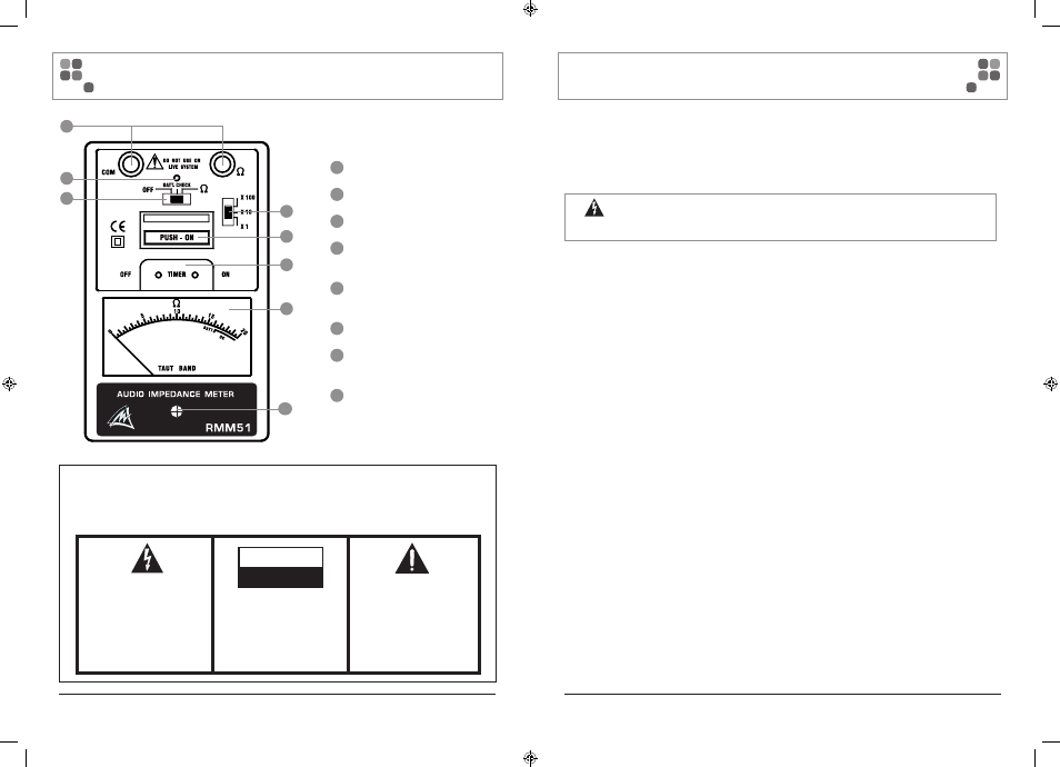
1
Terminals for test leads
2
Operation Indicator
3
Battery Check, On / Off
4
Ohm Range Selector
(x1, x10, x 100)
5
Push–On, press button
operation
6
Timer Control (On / Off)
7
Meter (Impedance /
Battery Check)
8
Meter zero adjust
3
2
1
6
5
4
8
7