Xrs rear panel powered version – Australian Monitor XRS Manual User Manual
Page 6
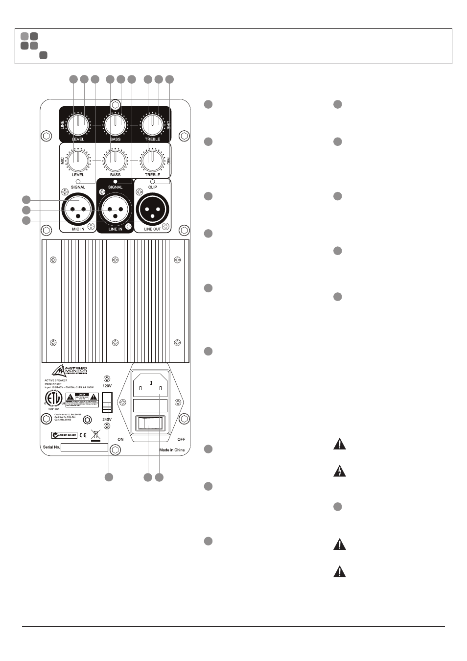
1
Mic In
Balanced XLR microphone input.
2
Mic Signal
Green LED Signal Present indicator for the
Mic input. It indicates signal present on the
input and is not affected by the level control.
3
Line In
Balanced XLR line level input.
4
Line Signal
Green LED Signal Present indicator for the
Line input. Indicates signal is present at the
input, it is not affected by the level control.
5
Line Out
LINE OUT is a line level output. This output
can be connected to the LINE IN on another
XRS Powered speaker to expand the
system.
6
Output Clip
Red LED clip indicator for mixed mic and
line audio signals. Some flashing of red
is acceptable on program transients.
Continuous flashing of red could indicate
that undue stress is being placed on the
speaker and will sound distorted. Turn
down the input level until the clip LED
is no longer lit.
7
Mic Level
Controls the level of the MIC input (1).
8
Mic Bass
Bass control for the MIC input (1). There is
12 dB of cut and boost at 100 Hz. This EQ
is the shelving type.
9
Mic Treble
Treble control for the MIC input (1). There is
10 dB of cut and boost at 10 kHz. This EQ is
the shelving type.
10
Line Level
Controls the level of the LINE input. (3)
11
Line Bass
Bass control for the LINE input (3). There is
12 dB of cut and boost at
100 Hz. This EQ is the shelving type.
12
Line Treble
Treble control for the LINE input (3). There is
10 dB of cut and boost at 10 kHz. This EQ is
the shelving type.
13
Power Switch
Mains power switch to turn the speaker
amplifier on and off.
14
IEC Mains Input Socket
XRS series powered speakers use a
standard IEC 3 pin mains socket. A standard
IEC mains cable is provided. The fuse
drawer contains the mains fuse and a spare.
The mains fuse is a time lag (slow blow)
HRC 20 x 5 mm ceramic or glass
type fuse.
XRS8P XRS10P XRS12P
120 V 2.5 A
2.5 A
3.15 A
240 V 1.6 A
1.6 A
5.0 A
IMPORTANT: Always replace the
fuse with one of the same value and type.
NOTE: Always disconnect power
to the amplifier before replacing fuses.
15
Voltage Select Switch
This switch selects the mains voltage for
your region. Choose either 240V or 120V.
IMPORTANT: Disconnect power
to the amplifier before operating this switch.
IMPORTANT: Always ensure that
the correct voltage for your area has been
chosen before connecting the unit to the
mains supply. Failure to do so may result
in personal injury or damage to the unit.
PAGE 6
XRS SERIES INSTALLATION AND OPERATION MANUAL
XRS REAR PANEL POWERED VERSION
15
13 14
10
11
12
7
8
9
2
4
6
5
3
1