Level the pump, Alignment procedure – Goulds Pumps VRS - IOM User Manual
Page 18
LEVEL THE PUMP
Leveling the pump is best performed without the drive and
motor installed. Loosen the (4) bearing frame hold down
bolts. Level the bearing housing to within 0.010 in.
(0.25 mm). Place shims between bearing housing and
support so that a gap of no more than 0.002 in (0.05 mm)
exists at any of the (4) anchor bolts when the bolts are
loose. Tighten the anchor bolts. If a floorplate is used, shim
each anchor bolt location so that a gap of no more than
0.002 in (0.05mm) exists at any of the anchor bolt locations
when the bolts are loose.
ALIGNMENT PROCEDURE
s
!
WARNING
Before beginning any alignment procedur, make sure
driver power is locked out.
Check the alignment twice:
•
Initial Alignment is done prior to operation when the
pump and driver are at ambient temperature.
•
Final Alignment is done just after operation when the
pump and driver are at operating temperature.
NOTE: Proper alignment is the responsibility of the
installer and user of the unit.
Accurate alignment of the equipment must be attained.
Trouble free operation can be accomplished by following
these procedures.
ALIGNMENT CHECKS
Initial Alignment (Cold Alignment)
•
Before Connecting Piping - To be sure alignment can be
obtained.
•
After Connecting Piping - To ensure pipe strains have
not altered alignment. If changes have occurred, alter
piping to remove pipe strains on pump flanges.
Final Alignment (Hot Alignment)
After First Run - To obtain correct alignment when both
pump and driver are at operating temperature. Thereafter,
alignment should be checked periodically in accordance
with plant operating procedures.
V-BELT DRIVE PUMPS
s
!
WARNING
Before beginning any alignment procedure, make sure
driver power is locked out.
1.
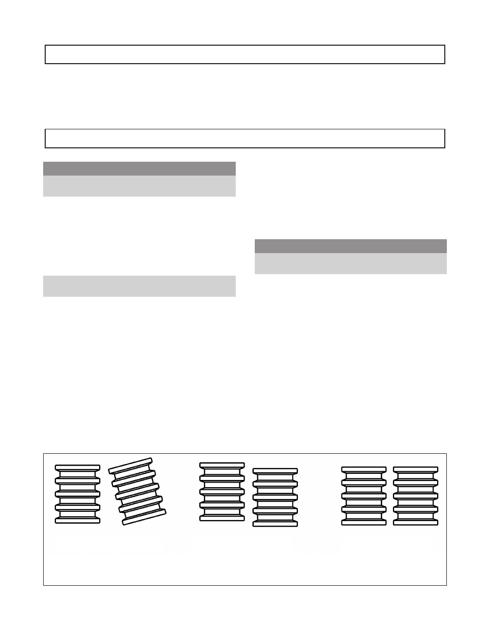
Place a straight edge across the top of the motor and
pump sheaves to measure the angular and parallel
misalignment (see Figure 2). Measure the gap between
the straight edge and the sheaves with feeler gauges. If
the gap exceeds 0.010 in (0.25 mm), adjust the sheaves
along the shafts to correct parallel misalignment and
shim the motor to correct angular misalignment.
2.
A dial indicator can be used to check runout on the
periphery and face of each sheave.
12
VRS IOM - 5/08
Angular Misalignment
Parallel Misalignment
Perfect Alignment
Figure 2
V-Belt Drive Alignment