Table 4 impeller clearances, Warning – Goulds Pumps 3996 - IOM User Manual
Page 26
Packing must not run dry. If the pumped liquid
is clean, gland leakage of 40-60 drops per minute
is satisfactory. If the liquid is dirty, connect a
clean liquid flush to the lantern ring connection
to keep solids out of the packing.
Occasionally, the stuffing box is below
atmospheric pressure (suction under vacuum,
etc.). Under these conditions, supply sealing
liquid through a line from the discharge of the
pump to the lantern ring connection. Leakage
from the box can be piped away through the ½
inch drain connection in the casing.
b.
Mechanical Seals - When mechanical seals are
supplied, they are installed in the pump.
Mechanical seals must not run dry, or in
abrasives. Connect recirculation, flush and/or
cooling flows as required, following instructions
on the seal print supplied for the order.
5.
Stuffing Box Lubrication/Cooling - Check to be
sure that any required auxiliary piping is installed and
functioning. If cooling and/or flushing from an
outside source is being used, establish these flows.
6.
Check Impeller Clearance -
!
The impeller clearance setting procedure must be
followed. Improperly setting the clearance or not
following any of the proper procedures can result
in sparks, unexpected heat generation and
equipment damage.
Prior to starting the pump, the impeller clearance
must be checked. The pump efficiency is maintained
when the proper impeller clearance is set. The
optimum hydraulic performance is attained by setting
the impeller front clearance at the factory to
predetermined limits which are consistent with
service conditions.
The maximum impeller setting should not be set
more than .005 inch (0.13) above values in Table 4 or
significant performance degredation will result.
!
Service temperature in an ATEX classified
environment is
limited to the area classification
specified on the ATEX tag affixed to the pump
(reference Table 1 in the Safety section for ATEX
classifications).
Also, for pumpage temperatures above 200° F (93°
C) the cold (ambient) setting must be increased per
Table 4. This is necessary to prevent the impeller
from contacting the casing due to differential
expansion from the higher operating temperatures.
Table 4
Impeller Clearances
Cold Temperature Clearances for Various
Service Temperatures
Service
Temperature
3996
ST
MT
inches
mm
inches
mm
From -20 to
150°F (-29 to
66°C)
0.005
0.13
0.008
0.20
Up to 175°F
(79°C)
0.005
0.13
0.008
0.20
Up to 200°F
(93°C)
0.005
0.13
0.008
0.20
Up to 250°F
(121°C)
0.006
0.16
0.009
0.23
Up to 300°F
(149°C)
0.007
0.19
0.010
0.26
Up to 350°F
(177°C)
0.009
0.22
0.012
0.29
Up to 400°F
(204°C)
0.01
0.25
0.013
0.32
Up to 450°F
(232°C)
0.011
0.28
0.014
0.35
Up to 500°F
(260°C)
0.012
0.30
0.015
0.38
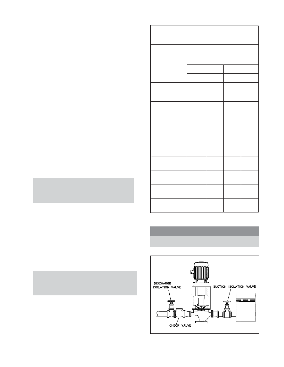
7.
Couple Pump and Driver
s
!
WARNING
Lock out driver power to prevent accidental rotation
and physical injury.
22
3996 IOM 9/2010
Fig. 8