Barksdale Series 20415 User Manual
Page 8
Barksdale, Inc. 3211 Fruitland Avenue, Los Angeles CA 90058 (800)835-1060 www.barksdale.com Bulletin No. 272367-B, 4-3-14
8
5.0 INSTALLATION
Make sure of ports are clean from debris that may have accumulated during storage or transportation.
Confirm system operating condition before installation and should be as per regulator specifications.
Caution: Pressure regulator should be installed in an assembly where the design pressure of the
system downstream of the device is lower than the pressure which can occur upstream of the device
and the system downstream should be protected by a safety accessory.
5.1 Install regulator horizontally or vertically using mounting holes (3/8-16 UNC-2B), 4 places.
5.2 Connect pipes – 1” NPT Inlet & Outlet, 1/2” NPT Vent to assemble regulator in your system.
SAE port option is available as per customer requirement.
5.3 If required, connect supply line to Air pilot or Hydraulic pilot motors for adjusting the pressure outlet set
point.
6.0 OPERATION
The Regulator 20415/L20415 is a 1” valve having options for manual operation, Air motor operation or
Hydraulic motor operated. The regulator comes set at the mid-point of the pressure range. Follow these
instructions to adjust the set point.
Warning
: Be sure that system pressure has been vented prior to operation.
6.1 For manual Regulator, loosen the locking handle, rotate the adjusting handle down to desired pressure and
set the locking handle tight.
6.1.1 To increase pressure, rotate handle clockwise, to decrease pressure, rotate the handle counter-
clockwise. Always tighten the locking handle after setting the regulator.
6.2 For Failsafe Regulator, the locking handle must be tight for the motors to engage. Note: If locking handle is
not fully engaged adjustment handle will spin freely during motor operation.
6.2.1 To adjust set point, apply pressure to pilot port "A" for an increase in set point and to port "B" for a
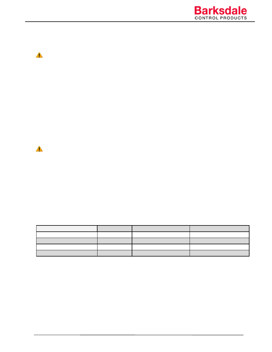
decrease in set point. Required range as in Table 2.
Table 2.
NOTE:
Regulator is designed to work with oil-based hydraulic fluid as well as with lubricated water.
6.3 Regulators work according to below flow patterns shown in Figure 5.
Figure 5.
Set Point operating Condition
Port Size
Pressure Range
Operating Temperature
Air motor Pilot Pressure
1/4" NPT
80 ‐ 120 PSI (5.5 ‐ 8.3 bar)
32° to +250°F ( 0° to +120°C)
For Land Version
1/4" NPT
80 ‐ 120 PSI (5.5 ‐ 8.3 bar)
‐30° to +185°F (‐34° to +85°C)
Hydraulic motor Pilot Pressure SAE for 3/8” Tube 400 ‐ 1600 PSI (27.6 ‐ 110.3 bar) ‐ 40° to +250°F (‐40° to +121°C)
For Land Version
SAE for 3/8” Tube 400 ‐ 1600 PSI (27.6 ‐ 110.3 bar) ‐30° to +185°F (‐34° to +85°C)