Myron L 4P (includes Addendum 10-01) User Manual
Page 6
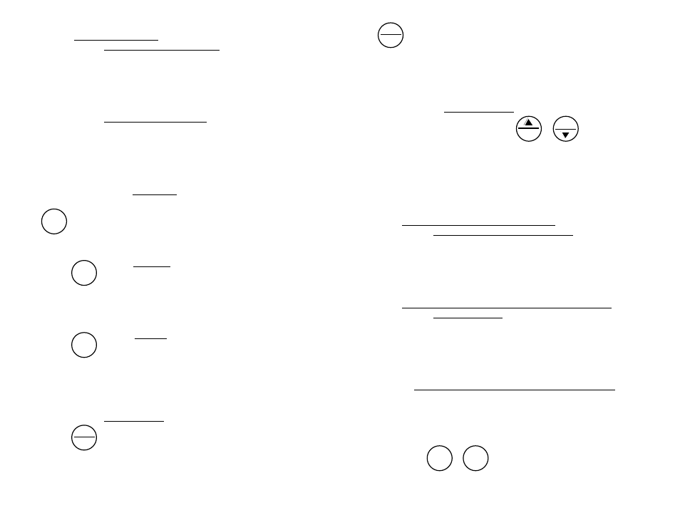
C. Operation of the Keys (See Instrument Illustration on page 1)
1. Measurement Keys in General
Any of the 3 measurement keys in the upper part of the keypad turns on
the instrument in the mode selected. The mode is shown at the bottom
of the display, and the measurement units appear at the right. Pressing a
measurement key does this even if you are in a calibration sequence and
also serves to abandon a change (ref. Leaving Calibration, pg. 14).
2. COND, RES and TDS keys
These 3 keys are used with solution in the Conductivity Cell.
Precautions:
•
While filling cell cup, ensure no air bubbles cling on the cell wall.
•
If the proper solution is not selected (KCl, NaCl, 442 or USER)
refer to Why Solution Selection is Available, pg. 10 and
Procedure to Select a Solution, pg. 10.
a. COND Key
Solution to be tested is introduced into the conductivity cell and a press
of
displays conductivity with units on the right. On the left is
shown the solution type selected for conductivity. An overrange
condition will show only [- - - -] (ref. Solution Selection, pg. 10).
b. RES Key
A press of
displays resistivity with units on the right. On the left
is shown solution type selected for resistivity (ref. Solution Selection, pg.
10). The range of display of Resistivity is limited to between 10 kilohms
(K
Ω
) and 30 megohms (M
Ω
). A solution outside that range will only show
[- - - -] in the display.
c. TDS key
A press of
displays Total Dissolved Solids with units on the
right. This is a display of the concentration of material calculated from
compensated conductivity using the characteristics of a known material.
On the left is shown solution type selected for TDS (ref. Solution
Selection, pg. 10).
3. CAL/MCLR key
A press of
allows you to enter the calibration mode while
measuring conductivity or TDS. Once in CAL mode, a press of this key
accepts the new value. If no more calibration options follow, the
instrument returns to measuring (ref. Leaving Calibration, pg. 14).
8
COND
R E S
T D S
CAL
MCLR
If
is held down for about 3 seconds, CAL mode is not entered, but
“
S E L
” appears to allow Solution Selection (ref. pg. 10) with the Up or
Down keys. As in calibration, the CAL key is now an “accept” key.
While reviewing stored records, the MCLR side of the key is active to
allow clearing records (ref. Clearing a Record/Memory Clear, pg. 16).
4. UP or DOWN keys
While measuring in any parameter, the or keys activate the
Memory Store and Memory Recall functions.
While in CAL mode, the keys step or scroll the displayed value up or
down. A single press steps the display and holding either key scrolls the
value rapidly.
While in Memory Recall, the keys move the display up and down the stack
of records (ref. Memory Recall, pg. 16).
III.
AFTER USING the ULTRAMETER
Maintenance of the Conductivity Cell
Rinse out the cell cup with clean water. Do not scrub the cell. For oily
films, squirt in a foaming non-abrasive cleaner and rinse. Even if a very
active chemical discolors the electrodes, this does not affect the
accuracy; leave it alone (ref. Cleaning Conductivity/TDS/Resistivity Cell
Cup, pg. 20).
IV.
THE SPECIFIC RECOMMENDED MEASURING
P R O C E D U R E S
If the proper solution is not selected (KCl, NaCl, 442 or USER), see
Solution Selection, Pg. 10.
N O T E : After sampling high concentration solutions or temperature
extremes, more rinsing may be required.
A. Measuring Conductivity/Total Dissolved Solids (TDS)
1.
Rinse cell cup 3 times with sample to be measured. (This
conditions the temperature compensation network and prepares
the cell.)
2.
Refill cell cup with sample.
3.
Press
or .
4.
Take reading. A display of [- - - -] indicates an overrange
condition.
9
COND
T D S
M S
MR
CAL
MCLR