Myron L 597 User Manual
Page 3
PLEASE READ THIS THROUGH COMPLETELY BEFORE
ATTEMPTING TO INSTALL OR OPERATE THIS SYSTEM.
DESCRIPTION
The Myron L Controlstik Rinse Tank System is a fully automatic
control which will greatly reduce the amount of water used in
continuous flow rinse tanks. At the same time, it automatically
maintains water quality, insuring effective rinsing in water up to
82°C (180°F). It operates on the electrical conductivity principle
and is fully stable and protected against all environmental
conditions including temperature, line voltage, water
contamination and corrosion.
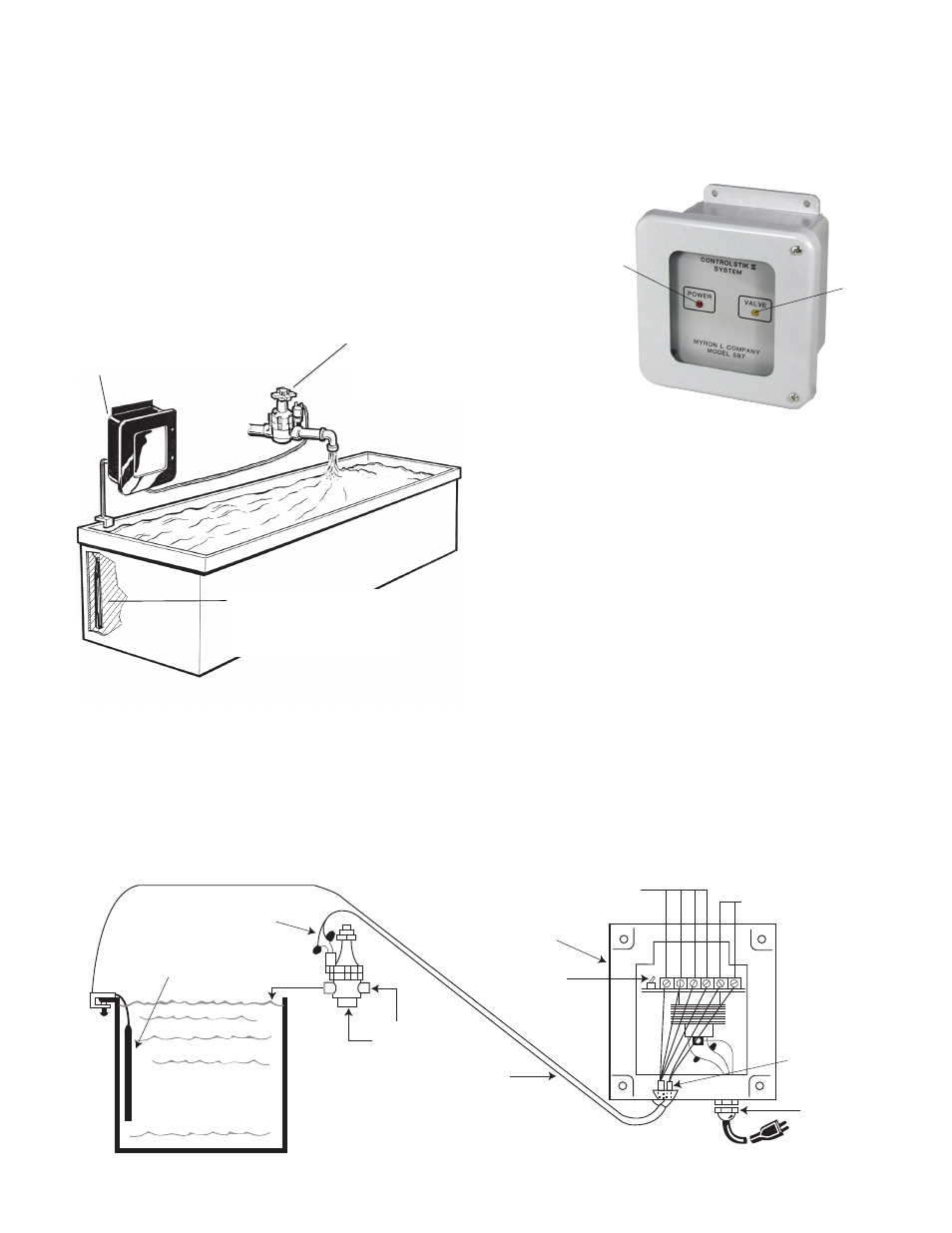
Controlstik Rinse Tank System has three major parts:
After installation, the Controlstik (sensor) is submerged in the
rinse water. When contamination (dragin) accumulates beyond
the point “safe” for good rinsing, the sensor automatically opens
the Solenoid Valve. Fresh water flows into the tank, and as
excessive contamination is diluted back to the “safe” level, the
sensor closes the valve, limiting water use.
INSTALLATION AND OPERATION PROCEDURES
A.
Mounting
Follow local electrical code
CAUTION: Do not apply power until all wiring has been
completed and connections checked.
1. Mount the Transformer Box near the correct AC power as
indicated on your unit. It may be hung on a wall, panel, or
post.
2. Hang Controlstik (sensor) in the tank by the cord, using the
securing clamp to hold the cord onto the edge of the tank.
The sensor should hang vertically, fully submerged at least
10 cm (4 in.) off the tank bottom and not closer than 60 cm
(2 ft.) to the inlet water line. If tank is small, locate sensor at
end opposite from inlet.
NOTE: If water rate is slow or if dragin rate and concentration
prevent good diffusion of contamination … the following
should be considered to insure the Controlstik senses
water that is “representative” of the entire tank:
1. Agitation - by air or other means
2. Installation of weir in tank perpendicular to water flow
3. Use of spider (sparge) on inlet
B. Piping
1. Install valve in inlet water line to rinse tank so that flow
direction is as indicated by the arrows on the top of
valve body.
2. Use Teflon tape on all connections and plug the unused inlet.
3. Insure flow control is at least partially open by turning
counterclockwise.
1. TRANSFORMER BOX
Reduces line power to safe
level for sensor and solenoid valve.
3. CONTROLSTIK SENSOR
Adjustable set-point minimizes
tampering. Two ranges built-in for
tap and purified water.
2. SOLENOID VALVE
1”, corrosion-resistant
with flow control and
manual override.
24V For safety.
2. Solenoid Valve
Water Inlet
(Options)
1. Transformer Box
Controlstik
Valve
Cap Plug
Strain Relief
Range Switch
105-125 VAC, 50/60 Hz (no cord/plug
supplied with 210-250 VAC 50/60 Hz model)
Low Voltage Wire
(not supplied)
3. Controlstik (Sensor)
completely immersed
CAUTION: Maximum
operating temperature
is 82ºC (180ºF)
R
ed
G
re
en
B
lac
k
W
hit
e
POWER
Light
1. TRANSFORMER BOX
VALVE
Light
1