Myron L 595 User Manual
Page 3
C.
Wiring
NOTE:
11
5 VAC systems — proceed to Section C.4
below.
1.
For 2
30 VAC systems: remove four screws in base
plate and lift out entire transformer electronics
assembly.
2.
If it is permissible for power line to share same opening
as valve and Controlstik sensor cables, this is easiest
method. If the 2
30 VAC power line must be separate,
CAREFULLY cut the edges of the preferred “knockout”
with a sharp knife to remove. The power line should
then be attached to the two transformer leads with wire
nuts. Be certain to also attach earth to the screw on the
side of the transformer.
3.
Return transformer electronics assembly to box and
screw down baseplate.
4.
Insert Controlstik cable through the slotted plastic plus
in box side. Connect the four color coded wires to the
terminals marked CONTROLSTIK.
5.
Obtain enough low voltage wire (at least 20 gauge/
.9398
mm diameter) to connect solenoid valve to
Transformer Box. Use pliers to attach spade lugs
(provided) to wire. Connect lugs to terminal strip
screws in box marked VALVE as in diagram.
6.
Recheck to be certain all connections are to correct
terminals.
CAUTION:
DO NOT short or connect the Controlstik
(sensor) to the terminals marked VALVE;
damage may result.
D.
Testing
1.
If controlling ordinary tap water, make sure Transformer
Box range toggle switch is set on “Hl” (toward back of
box). If controlling purified (such as deionized) water,
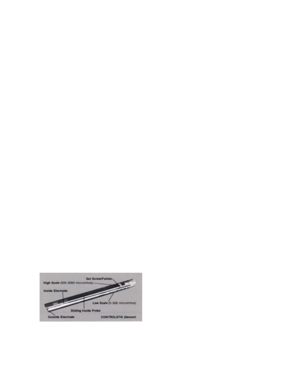
switch should be forward in “LO” position. Also,
Controlstik sensor pointer should face in direction of
High (500-5000
micromhos) or Low (5-500) scale to
agree with Box range switch setting. To change pointer
loosen set screw with 9/64 inch Allen wrench. Turn
pointer to opposite scale. Lift the rod to the other side
of the set screw and place back under the wide part of
the pointer plate. Retighten set screw with fingers,
allowing inside probe to move within sheath.
2.
Turn on the power by connecting the transformer box to
1
15 Volt AC (or correct voltage for model being
installed). POWER light on Transformer Box will glow.
to “short” the inside cone electrode to the outside band
electrode. This “short” will turn on valve; VALVE light on
Transformer Box will glow and valve will open.
4.
Remove “short” between electrodes. VALVE light will
go out and valve will shut off.
E. Initial Setting and Operation
1.
Fill pail with water from rinse tank inlet water line.
2.
Move inside probe of the Controlstik (sensor) back to
highest scale reading and submerge into pail of water.
3.
Slowly push inside probe toward opposite end,
stopping when Solenoid Valve triggers and VALVE light
goes on. Water will begin to flow into the tank. Read
scale.
4.
For the initial setting, move the inside probe back to
read at least 25% higher than the scale reading in step
3. Tighten set screw with 9/64" Allen wrench (finger
tight is not sufficient).
5.
Place the Controlstik (sensor) back into the rinse tank
as described under Section A. Mounting, number 2.
Fasten the cord with the securing clamp provided.
6.
Check setting and overall operation by rinsing parts or
by pouring a small amount of acid or alkaline solution
into the rinse tank to trigger the Solenoid Valve and
start water flow.
7.
Adjust valve flow control handle to obtain desired flow
rate. Check through at least one complete on/off
cycle. This valve can also be operated manually. To
disengage the solenoid (convert valve to manual
operation) hold the cross handle firmly and loosen
(counterclockwise) the bolt in the center of the stem.
Some water will spurt out at the stem while it is under
manual control.
NOTE: The best Controlstik (sensor) setting can be
determined with experience. Since the main
objective of the system is to conserve water use, a
high conductivity setting on the sensor is desirable
… as long as the water does not become too dirty,
preventing effective rinsing. However, if the sensor
is set too low, the water will flow continuously due
to the normal conductivity (total dissolved solids) in
source water - defeating the purpose of the
system.
MAINTENANCE
A.
Controlstik (sensor)
Although this system is very stable, the sensor should be
regularly checked for hard water scale, which will lower its
sensitivity. Scale can be easily removed by agitating sensor
in a 2-10% hydrochloric acid solution. If scale has been
allowed to build up for a long period, a bristle brush may
also be used. The Controlstik (sensor) may be
disassembled by removing the set screw and thoroughly
cleaned if it should accidentally become completely fouled.
B.
Valve
Should the Controlstik Rinse Tank System no longer
activate the Solenoid Valve when the inside probe is
intentionally “shorted,” unscrew the solenoid from the side
of the valve and check the chamber for any solid matter
which may prevent easy solenoid movement.
3.
Bring Controlstik (sensor) electrodes together by sliding
the inside probe completely forward. Use a screwdriver