Myron L 767 User Manual
Page 7
Installation
NOTE:
The 750/760 Series Conductivity Monitors are not designed to
operate with a Cell cable length that exceeds 100' (30 meters).
STEP 3 If at all possible, mount the Monitor at eye level for
viewing convenience.
2.2.1 SURFACE MOUNTING WITH SMP ASSEMBLY
NOTE:
A Surface Mounting Plate (SMP) will be required when access to
the far side of the mounting site is impractical. For 750 series
monitors, use the SMP-50 and for 760 series monitors, use the
SMP-60. Surface mounting will require two (2)
1
/
4
" X 20
mounting screws. (The mounting screws are packaged with the
SMP assemblies.) If an SMP is being used, the user must
supply four (4) additional screws or bolts. Their size is to be
determined by the user.
STEP 1 Select your mounting location. Mark and drill the four
(4) required mounting holes. For hole locations, use the
SMP as a template. Install any lags or threads required.
STEP 2 Drill the corner holes in the SMP according to the size
of the screws or bolts selected.
STEP 3 Attach and securely fasten the SMP to the Monitor
using the
1
/
4
" X 20 X
3
/
8
" screws provided.
STEP 4 Mount the SMP to the prepared site using the selected
screws or bolts.
2.2.2 SURFACE MOUNTING WITHOUT SMP ASSEMBLY
NOTE:
Surface mounting will require two (2)
1
/
4
“ X 20 screws of a
length equal to the thickness of the mounting site plus
3
/
8
”
STEP 1 Select mounting site location. Mark and drill the
required mounting holes. For hole drilling locations, see
Fig. 2-1.
STEP 2 Insert the
1
/
4
" X 20 screws into the holes from the side
opposite the mounting site.
STEP 3 Hold the Monitor in place while starting and tightening
the mounting screws.
2.2.3 PANEL MOUNTING
A panel mounting fastening kit is provided with all Conductivity
Monitors. Panel mounting will require the use of the fastening
kit’s two (2) 4-40 mounting screws/nuts or two (2) #4 x 1/2"
sheet metal screws. See Fig. 2-1 for panel cutout dimensions.
STEP 1 Select your mounting location. Mark the appropriate
panel cutout and complete the necessary panel cut.
STEP 2 Carefully unfasten and separate the Monitor’s front
panel from its enclosure.
STEP 3 Disconnect all panel cable(s)/wires from the Monitor’s
Control board.
STEP 4 Slide the enclosure through the panel cutout until its
flange contacts the panel.
STEP 5 Insert mounting screws through the flange mounting
holes and tightly secure.
STEP 6 Reconnect all panel cable(s)/wires and re-secure the
front panel.
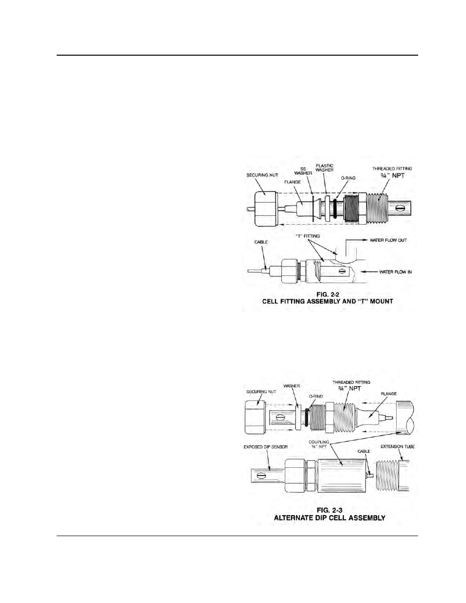
2.3 CELL INSERTION/DIP MOUNT ASSEMBLIES
A CS51 Cell’s mounting orientation must provide a continuous
and adequate circulation flow to prevent the trapping of air
bubbles within the Cell’s electrode area. Failure to do so will
result in conditions that will prevent the Cell from functioning
properly.
2.3.1 INSERTION MODE ASSEMBLY
STEP 1 Verify that the Cell’s Fitting assembly is properly
assembled as shown in Fig. 2-2.
STEP 2 Insert the Cell Fitting assembly into the “T” fitting as
shown in Fig 2-2 and tightly secure.
2.3.2 ALTERNATE DIP CELL ASSEMBLY
STEP 1 Verify that the Cell’s Fitting assembly is properly
assembled as shown in Fig. 2-3.
STEP 2 Insert and pull the Cell’s cable through the extension
tube and then tightly attach extension tube to Cell
assembly as shown in Fig. 2-3.
5