頁面 6 – MIPRO MR-811 Single-Channel Diversity Receiver User Manual
Page 6
MADE IN TAIWAN
MIXED
SEPARATE
ANTENNA A
ANTENNA B
OUTPUT A
OUTPUT B
LEVEL
DC IN
(12~15V)
OUTPUT MODE
SQ A
SQ B
+10dB
0dB
-6dB
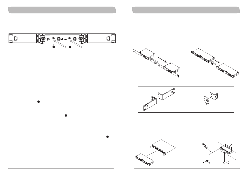
Rackmount Installation for Receivers
Receiver Rack-Mount Kits
Half-Rack Unit Receiver
!
Install the optional FB-71 rackmount kit & fasten with screws on both sides. (Figure
3)
1-Rack Unit Receiver
!
Install the optional FB-72 rackmount kit & fasten with screws on both sides. (Figure
4)
!
!
The rack mountable kits are pre-drilled with 4 opening holes to be fitted on an EIA
standard 19-inch rack case. (Figure 5)
For ideal reception and performance, install the receiver at least 1 meter (3 feet)
above the ground and away from EMI / RFI “noise” sources. In addition, place the
transmitter/microphone at least 1 meter (3 feet) away from the receiving antenna,
as shown. (Figure 6)
(Figure 4)
Ground
W
all
1
m
1m
1m
1m
(Figure 6)
(Figure 3)
(Figure 5)
Operation Instructions
(Figure 2)
7
7
1. Turn volume controls of the receiver and mixer in use to a minimum setting before
turn on the microphones or transmitters. After switches on the receiver, the power
switch red indicator illuminates to denote normal power status.
2. If RF LED indicators of the receiver light on before switches on the microphone or
transmitter, it indicates the receiver is receiving interference signals. This system
has Pitlotone and NoiseLock dual-squelch features and no noise output will occur. If
multiple channels are used and both RF and AF LEDs glow and interference noise
appear, simply adjust the Squelch controls clockwise until AF signal indicators to
extinguish. (Figure 2). However, by adjusting the squelch controls, it affects the
sensitivity level of the receiver, therefore, shorten the operating distance and
decreases the stability.
3. Under normal circumstances, the RF indicator lights up when a microphone or
transmitter is turned on near the receiver to indicate the receiver is ready for
normal operation. Once sounds to the microphone and the AF LED indicators will
glow according to the strength of sound level. If no LED glows or no sound outputs,
the system is not function properly, thus it must be checked.
4. The microphone output level needs to be adjusted at the amplifier or mixer. No need
to adjust at the receiver itself.
2
7
1
Mounts 1 half-rack receiver
into a single rack space
FB-71
FB-72
Mounts 1 1-rack receiver
into a single rack space
6
7
Single/Dual/Quad Channels Diversity Receivers
Single/Dual/Quad Channels Diversity Receivers