頁面 4 – MIPRO ACT-100A Dual-Channel Diversity Receiver User Manual
Page 4
4. Make sure the system performs correctly, please place the system away
from noise sources. Place the receiver at least 1 meter above the ground
and away from noise sources. Place the microphone at least 1 meter away
from the receiving antenna, as shown in Figure 5.
5. With two rackmount brackets installed, receiver can be mounted into an
EIA standard rackmount case, as shown in Figure 6. As an accessory, you
may purchase from nearest dealer a front antenna kit, which not only
allows easy front antenna installation, but also improves efficiency of
signal reception.
(c) Guitar Output: Using audio output cable attached with "PHONE PLUG"
type, plug one end from the unbalance-mixed output jack of a receiver,
and the other end to the input jack of a guitar amplifier.
Switch the Level Switch to "+10dB" position.
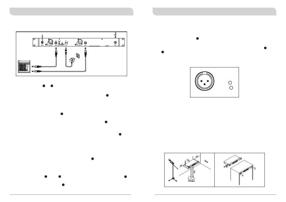
(d) Balanced Output: Using audio output cables attached with "XLR" or
"Cannon" type, connect one end from the balanced output jacks B and
A of the receiver, and the other end to the "MIC IN" input jack of the
mixer or amplifier, as shown in Figure 3. (The characteristic of the 3-pin
connector is as shown in Figure 4)
3: COLD
-
+
1: GND
2: HOT
3
2
1
(Figure 4)
(Figure 5)
(Figure 6)
2. Installation Of The Receiver
(Figure 3)
(a) Unbalanced Level Switch Setting Position: When connecting from
receiver's unbalanced output to the "AUX-IN" jack of a mixer or
amplifier or "Electric Guitar", switch the Level Switch to "+10dB"
position. Low sensitivity may occur if switch to the wrong level
position. When connecting from receiver's unbalanced output to the
"MIC-IN" jack of a mixer or amplifier; switch the Level Switch to
"0dB" position. Overload distortion may occur if switch to the wrong
level position. When using electric guitar, don't use "0dB" or "-6dB"
position as it may have generated insufficient level. There are lots of
amplifiers for Karaoke machine in today's market, however, gain of
amplifier's "MIC IN" is not unified. Therefore, if distortion is
encountered, please switch the Level Switch to "-6dB" position.
(b) Connection for Unbalanced Outputs: When the receiver is near the
input/output jacks of mixers/amplifiers, or both systems use phone
jacks, one can connect two separate output cables to unbalanced
output jacks B and A in the receiver. If output mode selector
switches to "MIXED" mode, connect only one unbalanced cable to
unbalanced output jack B as shown in Figure 3.
1. Install two antennas, perpendicularly and fully extended, to the antenna
input connectors & at the rear panel of the receiver, as shown in
Figure 3. (ACT-100A/ACT-100B)
2. Connect the AC/DC adapter cable to DC 12V INPUT JACK , then plug
the adapter unit into an appropriate AC outlet with caution to the correct
voltage under both AC outlet and adapter marked, as shown in Figure 3.
3. Audio Output Connection:
22
24
25
26
27
29
30
25
25
25
24
25
23
28
4
5
Dual Channel Wireless Receiver
Dual Channel Wireless Receiver