頁面 3, Anoise sensitivity a noise sensitivity b – MIPRO ACT-100A Dual-Channel Diversity Receiver User Manual
Page 3
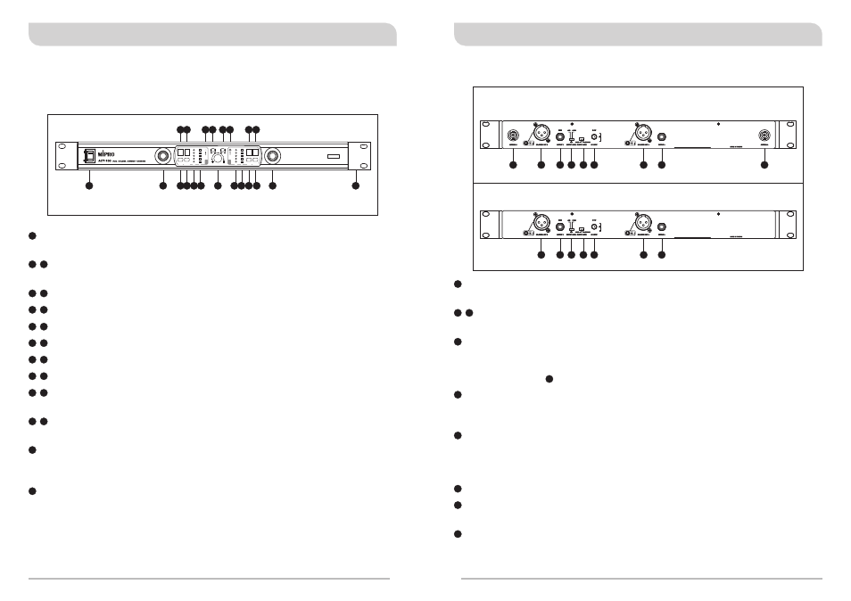
B. Rear Panel
1. Part Names And Functions
A. Front Panel
(Figure 1)
Power Switch & Indicator: When switch is turned on, red indicator
illuminates to denote normal power status.
ACT Button: Press to synchronize transmitter and receiver frequencies
autotically.
Group Button: For selection of Group.
Channel Button: For selection of Channel.
Group LED Screen: Indicates the selected numeric group.
Channel LED Screen: Indicates the selected numeric channel.
RF Signal Indicators: Indicates received RF signals from transmitters.
Audio Signal Indicators: Indicates the microphone signal.
Sensitivity Adjuster: To adjust receiver sensitivity that ensures no
noise output if receiver is not receiving signals from transmitters.
Microphone Balance Volume Adjuster: Allow users to adjust the
mixed volume level of two microphones to a balanced or different level.
Adjuster is factory preset for balanced level.
Rackmount Bracket: To install the receiver into an EIA 19-inch
standard rack case.
Noise Warning Indicator: Red light glows denoting the presence of
interference.
B
A
BALANCE VOLUME
CHANNEL
RF
AF
GROUP
RF
AF
GROUP
CHANNEL
B
A
NOISE
SENSITIVITY A
NOISE
SENSITIVITY B
(Figure 2)
ACT-100
ACT-100A/ACT-100B
20
21
22
23
23
24
24
25
25
26
26
27
27
28
28
29
29
30
15 16 17
14
11
8
7
4
3
2
1
5 6
9 10 12 13
18 19
21
15
16
17
14
11
8
7
4
3
2
1
5
6
9
10
12
13
18
19
20
Antenna B input Connector: To install Antenna B. (ACT-100A/
ACT-100B)
Balanced Audio Output Jack: With Cannon / XLR type connector
provides balanced audio output signal from this jack to the amplifier.
Unbalanced Audio Output Jack B: 1/ 4λ Phone Jack provides
unbalanced audio output signal from Channel B or the mixed output
signals from Channel A & B. (Depend on the position of the unbalanced
mixed switch .)
Unbalanced Level Switch: "0dB" selection is for "Microphone-level"
output. "+10dB" selection is for "AUX level" output. "-6dB" selection is
for half of cable microphone volume.
Unbalanced Mixed Switch: System will have mixed AF output when
switch to "MIXED" position. AF signal from both Channel A & B will be
transmitted from "Output B" only. When switch to "SEPARATE", AF
signal will be transmitted separately from "Output A" and "Output B".
DC Input Jack: To connect 12V/1A DC from the AC/DC adapter.
Unbalanced Audio Output Jack A: 1/ 4λ Phone Jack provides
unbalanced audio output signal from Channel A.
Antenna A Input Connector: To install Antenna A. (ACT-100A/
ACT-100B)
22
23
24
25
26
27
29
30
28
26
2
3
Dual Channel Wireless Receiver
Dual Channel Wireless Receiver