Dero decker, American bicycle security company – American Bicycle Security Company Dero Decker User Manual
Page 4
American Bicycle Security Company
P.O. Box 7359
Ventura, CA 93006
Ph: (800) 245-3723 or (805) 933-3688
Fax: (805) 933-1865
Dero Decker
Installation Instructions
Single Sided
1. Refer to setback diagrams before installation to ensure sufficient space.
Installation surface must be level. If surface is not level, contact an American
Bicycle Security Company representative for workable solution.
Tools Needed:
Hammer drill
Masonry bit, 3/8”
Hammer
Socket wrench
Sockets, 3/8”, 15/16”
Socket extension, 4”
Wrench, 15/16”
Tape measure
Carpenter’s square
Chalk line
Marker
Level
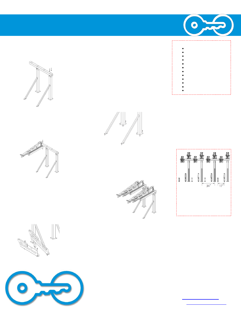
2. Place both Uprights in position and
place the Cross Beam on top of the
Uprights. Secure the Cross Beam to each
Upright with at least two 5/8 x 5.5” bolts
placed diagonally from each other.
3. After checking that the unit is square and that the
minimum setbacks have been achieved, anchor the
Uprights to the floor with 5 wedge anchors each.
4. Starting at one end of the CROSS BEAM and working
your way to the other, place a CANTILEVER ASSEMBLY
and secure it with four 5/8 x 5.5” bolts. Check to make
sure the CANTILEVER ASSEMBLY is at 90º to the CROSS
BEAM. After tightening the fourth bolt, retighten all four
bolts.
5. Place and secure the rest of the CANTILEVER
ASSEMBLIES with alternating Up and Down CANTILEVER
ASSEMBLIES.
6. Place the LOWER TRAYS in position on the ground with
alternating UP and DOWN LOWER TRAYS. The LOWER
TRAYS should be in between the CANTILEVER
ASSEMBLIES. The front edge of the UP and DOWN LOWER
TRAYS are coincident and 62” from the back edge of the
UPRIGHT base flange. Secure the LOWER TRAYS to the
ground with wedge anchors.
When placing multiple units in
a row, the space between
uprights of separate units
should be 34” center to
center.