Vaddio Hot-Shot Preset Camera Controller User Manual
Page 9
Hot Shot Preset Camera Controller
Hot Shot Preset Camera Controller - Installation and User Guide - Document Number 342-0124 Rev D Page 9 of 16
INSTALLATION Step-by-Step Example with Codec:
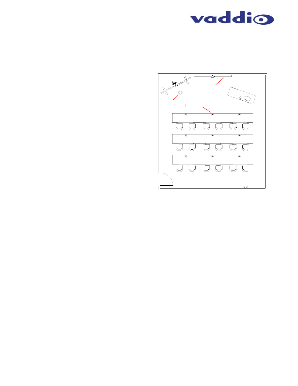
This example is a room system using a Cisco C60 codec
with two (2) cameras (student camera located in front and
the instructor camera in the rear of the room). There are
18 students and 9 tables with two students to a table and
each table has a push-to-talk microphone (9 total mics)
set to momentary mode. The microphone mixer/switcher
is the Vaddio MicVIEW. The instructor has a front of the
room lectern which will be a default position and a
whiteboard area that will be covered by a Vaddio
AutoVIEW IR Sensor. Monitors are at the front of the
room. The instructor has a mic at the lectern position that
is always on - or - has a wireless lapel mic plugged into
MicVIEW Input # 1 which is always on. The equipment is
in the lectern or small rack nearby.
Step 1:
Install the videoconferencing system as described by the
system manufacturer.
Step 2:
With the codec IR remote control, set the preset
positions in the codec preset memory reflecting where
each preset position is located in the desired order that
the triggering is to be activated. In this case the Instructor
position is Preset 1 on Camera 2, the IR Sensor near the
whiteboard is Preset 2 on Camera 2 and the Students on
Presets 3 through 11 using camera 1. The presets are
stored in the codec.
Step 3:
Connect the Hot-Shot to the RS-232 Port of the TANDBERG codec, in this case with a Female to Male 9-pin
straight through RS-232 cable (PN 998-1002-232). Set the dip switches for the TANDBERG C-Series codec (first
four dip switches to Up, Down, Up, Up). Set dip switch 7 to Last Step trigger mode (Up). Set dip switch 8 to
enable Default Idle Return to activate Preset 1 (Up) so that if nothing is triggered, then the codec will return to
Preset #1 and display the instructor position. Finally, set dip switches 9 and 10 (both Up) to Hot-Shot Address
Master 0, since only one Hot-Shot is being used.
Step 4:
Connect the IR Sensor leads (+ to connector 2 and - to GND) to the Hot-Shot. Connect the MicVIEW logic out
triggers 3 through 11 to terminals 3 through 11 on the Hot-Shot and the GND wire of the MicVIEW to the GND of
the Hot-Shot. Leave Terminal 1 of the Hot-Shot empty since Default Idle Return to Preset 1 is on and is the
Instructor on Preset 1 of the codec.
Step 5:
Once all the presets have been saved, and the trigger connections made, then power down the system
completely. To reboot the system, turn on the Hot-Shot, and then turn on the codec. The system should be
ready for use. Test each trigger and fine tune the camera presets as needed.
Notes:
To use the videoconferencing system without triggers, simply touch the blue LED button on the front panel of the
Hot-Shot to disable the triggers/presets. When the Blue LED is off, the preset triggers are disabled.
The camera presets are stored in the codec and can easily be overwritten by users that are unfamiliar with the
room automation set-up. Please keep a record of the preset numbers and locations available to quickly
reprogram the codec if some of the presets are inadvertently erased or changed.
Mics x 10
Lectern
Whiteboard
(P2)
Instructor
Camera (2)
Student
Camera (1)
Displays
IR
Sensor
Instructor
Position (P1)
P3
P5
P4
P7
P6
P1
0
P8
P9
P1
1
Basic Hot-Shot Room Example with Codec