Diagram - new application - single camera system, Setting up the hot-shot preset camera controller – Vaddio Hot-Shot Preset Camera Controller User Manual
Page 7
Hot Shot Preset Camera Controller
Hot Shot Preset Camera Controller - Installation and User Guide - Document Number 342-0124 Rev D Page 7 of 16
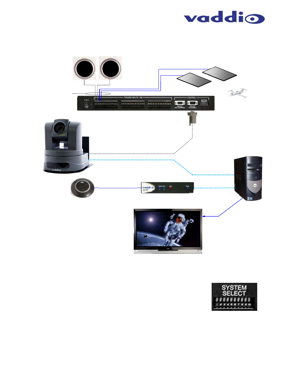
Diagram - New Application - Single Camera System:
Hot-Shot and Vaddio HD-USB PTZ Camera,
AutoVIEW IR Sensor, StepVIEW Mats
Setting Up the Hot-Shot Preset Camera Controller
The Dip Switches:
There are ten (10) dip switches on the rear panel that configure the Hot-Shot Preset
Camera Controller. Configuration is not automatic, but it is easy to understand. The
dip switches control the following functions:
Dip Switches 1 through 5:
Assigns the RS-232 output preset codes
Dip Switch 6:
Not used - for future features
Dip Switch 7:
Assigns the trigger processing order (Last Step or First Step)
Dip Switch 8:
Assigns Preset #1 to Default Idle Return (returns to preset #1 with no trigger)
Dip Switch 9 and 10:
Sets the Hot-Shot Address and Master/Slave configuration when cascaded
H
OT
-S
HOT
Preset Camera Controller
StepVIEW Mats
Teacher’s Locations
Front and White Board
AutoVIEW IR
Sensors
Other Room
Locations
Preset
Triggers
RS-232 Camera Presets
USB.2.0 Video
Using UVC Drivers
USB.2.0 Audio
Using UAC Drivers
HD Video
PC with USB 2.0
Recording Application
EasyUSB Mixer/Amp
EasyMic MicPOD
with 3-Integrated
Echo Cancellers
Cat-5e
HD-USB PTZ
Camera
Simulated Video Feed
998-1001-232
Control Adapter
Audio Serving Suggestion: Vaddio EasyUSB Mixer Amp and EasyMic MicPOD
Learjet not
included