Dip switch configuration, 8 dip switch configuration – Avenview C-HDSDI-HDMI User Manual
Page 6
www.avenview.com
6
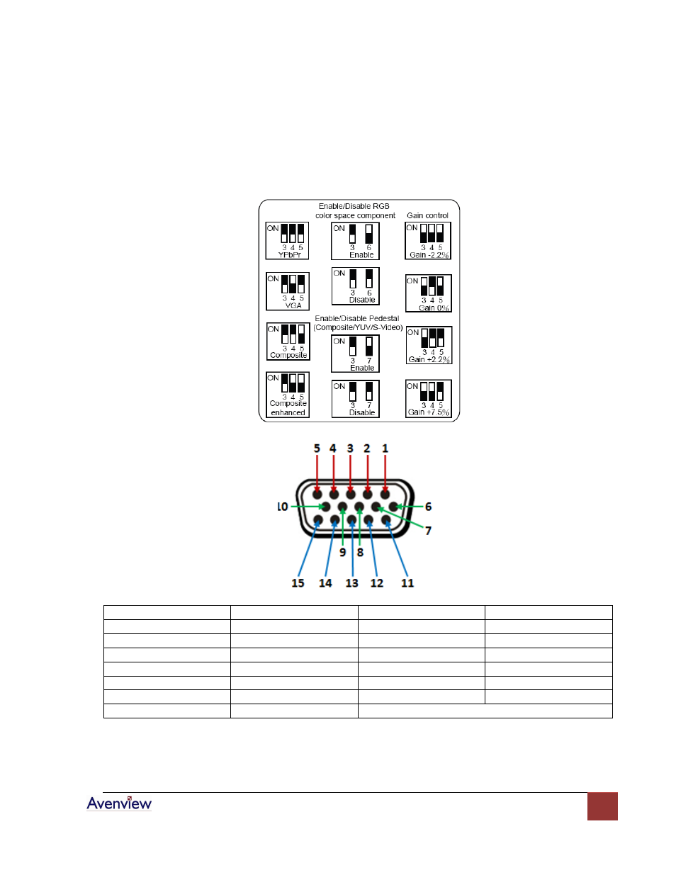
1.8 DIP Switch Configuration
8 Pin DIP switch is used for user interface, and users can access this switch from the bottom of the unit.
Output formats, video patterns, SD pedestal, SD Wide, PAL mode, Component / RGB, SD Component or SD
Composite, YC ON/OFF etc.
Pin 1
Pr / Red
Pin 2
Y / Green / Composite
Pin 3
Pb / Blue
Pin 4
Ground
Pin 5
Ground
Pin 6
Ground
Pin 7
Ground
Pin 8
Ground
Pin 9
+5V
Pin 10
Ground
Pin 11
Ground
Pin 12
Reserved
Pin 13
Horizontal SYNC
Pin 14
Vertical SYNC
Pin 15
Reserved