Panasonic FV-08VF2 User Manual
Page 8
inches mm
(
)
2-Long screws
(M4X30)
Adaptor
Suspension bracket &
I II
Ceiling joist
Adaptor
2-Long screws
(M4X30)
Fig. 8
B
A
7/8 (21.6)
13 1/4~15 1/2 ( 336~394 )
16 1/2~18 3/4 ( 419~480 )
21 1/4~23 1/2 ( 540~597 )
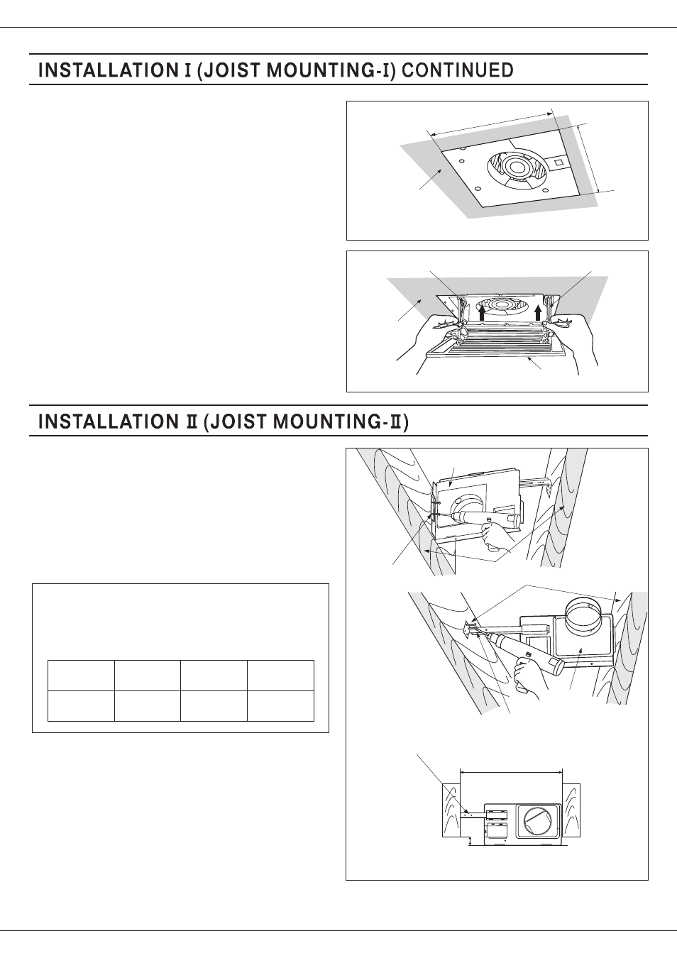
8. Finish ceiling work. Ceiling hole should be aligned
with the edge of the flange. (Fig. 6)
9. Insert mounting springs into slots as show and
mount grille to fan body. (Fig. 7)
8
Fig. 7
Ceiling
Slot
Mounting spring
Grille
1. Open the orifice cover, disconnect plug connector
from receptacle and remove adaptor from fan body
before starting installation.
2. Insert the suspension bracket into the adaptor and
secure it to joists by using long screws(M4X30) (Fig. 8)
Keep the distance B (7/8 inch, 21.6mm) for the
thickness of ceiling board.
3. Follow steps 5 to 7 of the Installation (page 7) to
complete the duct work and wiring.
I
If spacing A between joists is 21 1/4 to 23 1/2
inches, connect suspension bracket
and
(C4 mark to C4 mark) according to page. 8
Select the suspension bracket according to
spacing A as show below.
II
III
suspension
bracket
suspension
bracket
I
suspension
bracket
III
suspension
bracket
&
II III
Spacing A
between Joists
inches (mm)
13 1/4~15 1/2
( 336~394 )
16 1/2~18 3/4
( 419~480 )
21 1/4~23 1/2
( 540~597 )
Fig. 6
Ceiling
10 7/8
(275)
10
7/8
(275)
inches (mm)
4. Insert
to fan body
(refering to step 2 of Installation , page 6)
the suspension bracket in
I