3 installing cpu and heatsink – Asus AP1600R User Manual
Page 22
22
Chapter 2: Hardware Setup
2.3
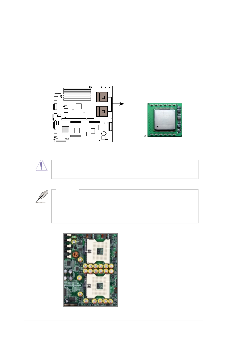
Installing CPU and heatsink
The 604-pin Zero Insertion Force (ZIF) sockets on the PR-DLSR motherboard
support dual Intel
®
Xeon™ processors. This section tells you how to install a
CPU. Refer to the motherboard user guide for more information.
A CPU has a gold triangular mark on one corner. This mark indicates the
processor Pin 1 that should match a specific corner of the CPU socket.
Incorrect installation of the CPU into the socket may bend the pins
and severely damage the CPU!
CAUTION
PR-DLSR
®
PR-DLSR Socket 604
Xeon Processor
Gold Mark
CPU Socket 1
(outer socket)
CPU Socket 2
(inner socket)
The motherboard supports either one or two CPUs. If you are
installing only one CPU, you MUST install it in CPU socket 1.
There is no need to install a CPU terminator even if you are installing
only one CPU.
NOTES
- CG8565 (410 pages)
- CG8565 (246 pages)
- CS5120 (1 page)
- CS5111 (26 pages)
- ET1611PUK (38 pages)
- S2-P8H61E (80 pages)
- P2-P5945GCX (90 pages)
- P2-PH1 (80 pages)
- P1-P5945G (80 pages)
- CG8270 (534 pages)
- CG8270 (362 pages)
- CG8270 (218 pages)
- CG8270 (536 pages)
- CG8270 (72 pages)
- CG8270 (76 pages)
- P3-P5G31 (100 pages)
- P3-PH4 (80 pages)
- P2-M2A690G (8 pages)
- P2-M2A690G (80 pages)
- P4-P5N9300 (82 pages)
- P4-P5N9300 (1 page)
- P2-P5945GC (92 pages)
- P1-P5945GC (92 pages)
- P3-P5G33 (98 pages)
- T3-P5945GC (80 pages)
- T3-P5945GCX (80 pages)
- P2-M2A690G (94 pages)
- T3-PH1 (82 pages)
- T3-PH1 (80 pages)
- T5-P5G41E (76 pages)
- T5-P5G41E (82 pages)
- S1-AT5NM10E (68 pages)
- P6-P7H55E (67 pages)
- ES5000 (174 pages)
- T4-P5G43 (104 pages)
- T-P5G31 (92 pages)
- BT6130 (60 pages)
- BT6130 (54 pages)
- BT6130 (2 pages)
- CG8265 (350 pages)
- CG8265 (210 pages)
- CM1740 (198 pages)
- CM1740 (330 pages)
- CM1740 (70 pages)
- P6-M4A3000E (59 pages)