Computer interface port – APC 650 User Manual
Page 21
17
English
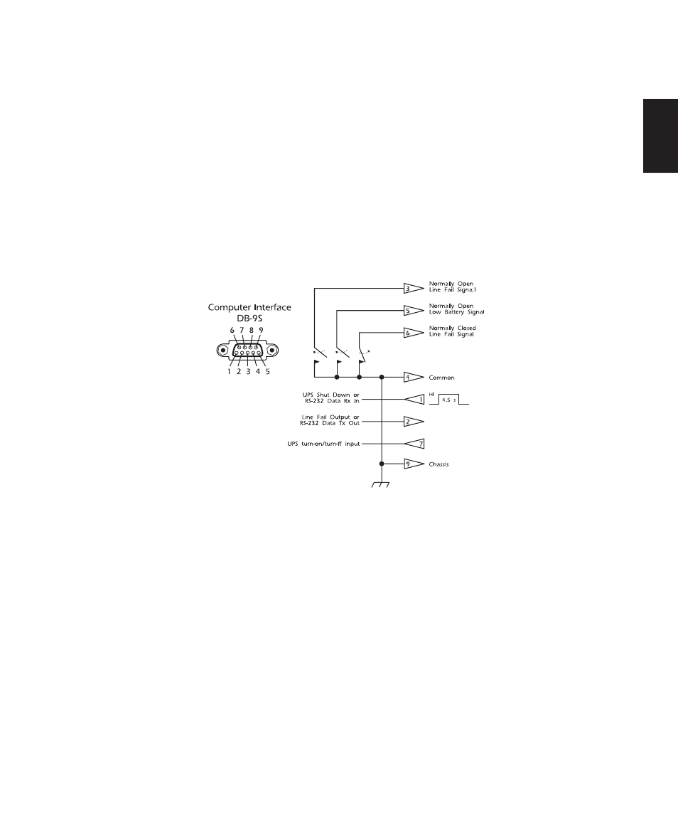
Computer Interface Port
The computer interface port has the following characteristics:
n Pins 3, 5, and 6 are open collector outputs which must be pulled up to a common referenced
supply no greater than +40 Vdc. The transistors are capable of a maximum noninductive load
of 25 mAdc. Use only pin 4 as the common.
n Pin 2 generates a low to high transition at RS-232 levels when the UPS signals that it is on-bat-
tery. Pin 2 is also the RS-232 data output (TXD).
n The UPS will shut down when a high RS-232 level is sustained on pin 1 for 4.5 seconds. The
UPS responds to this signal only after a delay and during a power utility failure (when the
UPS is operating on battery). Pin 1 is also the RS-232 data input (RXD).
n Apply a momentary (approximately 1 second) high RS-232 level to pin 7 to turn on the UPS
and any attached loads. A momentary low turns off the UPS and its load. Pin 7 should be un-
connected normally.