American Aldes Hood Liner User Manual
Page 2
CHOOSING THE RIGHT REMOTE MOUNT BLOWER
Below is a chart of the recommended ALDES fans that can be used with the HLS & HLD Series
range hood liners. Some models are for mounting remotely in the attic. Other models are used
when installation requires a roof mount or wall mount fan.
Model
Location Mounting
Airflow @ 0"
Typical Airflow†
A-6
interior
inline
257
190
A6HP
interior
inline
392
275
XMV-A6HP
exterior
wall
381
330
RMV-A6
exterior
roof
227
205
HLS 30 & HLS 36
Model
Location Mounting
Airflow @ 0"
Typical Airflow†
A8-HP
interior
inline
521
450
AD-8HP
interior
inline
836
650
XMV-A8HP
exterior
wall
435
370
RMV-A8HP
exterior
roof/wall
401
350
HLD 36
Model
Location Mounting
Airflow @ 0"
Typical Airflow†
A-10HP
interior
inline
590
525
AD-10HP
interior
inline
1266
1020
RMV-A10HP
exterior
roof/wall
753
721
RMV-A10HPT
exterior
roof/wall
1008
919
HLD 42 & HLD 48
†Typical airflow is an estimate based on a system with 20-feet of duct, two 90 degree elbows,
backdraft damper, roof cap and filter.
*Representative of full-speed operation @.375 s.p. in a typical installation.
NOTE: Due to the large volume of air that these remote blowers move, it is important that a
source of sufficient makeup air is available to avoid backdrafting in the house.
PART 2 Electrical Connection
WARNINGS:
1. Ensure that the power supply is disconnected before proceeding.
2. Verify that the power supply matches the ratings found on the appliance data label before
proceeding.
3. The complete appliance must be properly grounded at all times when electrical power is
applied.
4. Do not ground the appliance with the neutral (white) house supply wire. A separate
ground wire must be utilized.
5. Failure to complete electrical connections properly may result in damaged or nonfunc-
tional systems. Follow instructions carefully to ensure proper installation.
• It is the owner’s responsibility to ensure that a qualified electrician performs the electrical
connection of this appliance. The electrical installation, including minimum supply wire
size, must comply with the National Electric Code ANSI/NFPA 70-1990 (or latest revision)
and local codes and ordinances.
• A copy of this standard may be obtained from National Fire Protection Association, 1
Batterymarch Park Quincy, Massachusetts 02269-9101
INSTRUCTIONS:
1. A 15 to 20 amp electrical service is recommended for proper electrical supply. Before
determining, calculate amp ratings based on the product label found on the liner and the
ventilator. (Always observe local building codes).
2. Always use a dedicated circuit.
3. Line load is calculated by adding the amperage of the halogen lights to the rated amper-
age of the ventilator (either in-line or roof top). If the ventilator is rated in watts rather than
amps, divide the watts by 120 and this will give you the amperage rating.
4. The ALDES liner is supplied with a 5.0 amp variable speed fan control. Make sure the
rated amperage on the ventilator does not exceed 5.0 amps.
5. The ALDES liner has been designed to accommodate several different motor speed
controls, (for example Thermador
TM
model CTR3-Q). Always consult the manufacturer’s
installation instructions when substituting control switches.
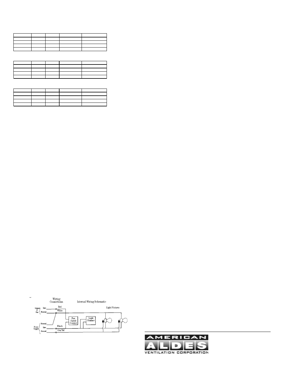
6. Wire connections: (Figure 2)
• Black — 120 VAC from electrical panel (black)
• White — Neutral from electrical panel (white)
• Green — Ground from electrical panel (green)
• Red — 120 VAC variable control to 120 VAC of ventilator
Figure 2
CAUTION: The neutral wire (usually white) for the ventilator must connect to the same neutral
wire that comes from the electrical panel to the liner. It is recommended to run a white
neutral wire from the liner’s white neutral wire along the same path as the red wire from
the liner’s variable speed control to the ventilator.
1259
PART 3 Securing the Liner
SECURING INSTRUCTIONS:
1. Because the professional series liner was designed for custom applications, no mount-
ing holes have been predrilled. This allows you to attach the liner in the areas of the
canopy which have ample support and backing.
2. You must secure the liner through both right and left sides, through the back and through
the top.
3. Remove the filters. Mark and drill screw holes through the liner as required for custom
canopy. Secure the liner by driving screws (provided by others) through the stainless
steel into the framing and backing.
CONNECTING TO THE VENT PIPE:
1. Insert the tabbed end of the galvanized Start Collar into the round hole in the outside top
of the liner.
2. Bend all of the tabs firmly in places against the inside top of the liner. Sheet metal screws
should be placed equidistant through 3 or more tabs. CAUTION: For safety of the
person cleaning this liner, neatly cover the well-flattened tabs with 2 or more layers of
metal tape.
3. Attach the other end of the Start Collar to the range hood vent with a minimum of 3
equidistant screws and metal tape.
PART 4 Use & Care
OPERATING CONTROLS:
1. Always activate the ventilator whenever using cooking appliances.
2. Activate the ventilator a few minutes before starting to cook to establish an airflow pattern within
the room.
3. Adjust the fan speed according to the amount of cooking exhaust.
4. Adjust the dimmable halogen lights as desired.
5. Eliminate air currents in the hood vicinity by shutting nearby windows and doors, turning off
ceiling fans and closing the adjacent heating and air conditioning outlets.
6. Place your largest pans, skillets and stock pots on the rear burners whenever possible.
WARNING: DO NOT operate the vent system without the filters in place, or with dirty, grease
laden filters.
ENERGY SAVING TIPS:
1. Do not operate the blower at a speed that is higher than necessary to remove the cook-
ing exhaust. Running at excessive speeds removes more air from the inside of the
house that must be replaced by outside air. This may be especially costly when your
home’s heating or air conditioning system is in operation. Turn off the unit once the
smoke and cooking odors have been eliminated.
2. Clean filters and grease laden surfaces often to improve efficiency.
3. Always use lids on cookware to retain heat and moisture.
4. Minimize the amount of liquid used to cook food.
5. Select cookware of proper size, material and construction for the cooking task being
performed.
CARE & CLEANING:
1. Proper cleaning is necessary to maintain performance and appearance, while also en-
suring safe operation. The frequency of cleaning should be adjusted according to the
type and amount of cooking. Best results will be achieved by cleaning soiled compo-
nents as soon as possible.
2. Filters must be cleaned regularly. Remove one filter at a time. On models HLD-36, 42,
& 48, grasp the filter handle and gently pull toward you, then down and back. Filter
should be installed with the handle in the rear filter slot. On model HLS-30, insert a blunt
knife into the small slot in the front edge of the filter. Push down and back. Filter should
be installed with small slot at the front of the filter.
3. The filters may be cleaned by hand washing in hot water using a mild detergent solution,
or by placing them in the top rack of an automatic dishwasher. Dry the filters completely
before using again.
4. Stainless steel surfaces should be cleaned with a solution of mild detergent and warm
water. Rinse and dry with a soft lint-free cloth.
CAUTION: Do not use any type of pad
that will scratch the liner.
5.
CAUTION: If a commercially available stainless steel cleaner is used, it is important to
read the labels for chlorine compounds. Chlorine is a corrosive substance. If these
compounds are present, rinse thoroughly and dry with a soft lint-free cloth. Follow polish
manufacturer’s instructions.
6. Always wipe stainless steel surfaces with the grain. Never wipe across the grain.
7. After cleaning, reinstall the filters carefully.
REPLACING LIGHT BULBS:
Par 20 halogen lamps are available in many different styles and sizes. Following is a list recomended
by the manufacturer:
• Phillips MASTER Line 50 watts 120V
• Felt Electric 50 watt 130V
• Industrial Grade Premium Quality
TM
P.Q.L. Incorporated Code 83009
4537 NORTHGATE COURT
SARASOTA, FL 34234-2124, USA
Tel: 941-351-3441 Fax: 941-351-3442
www.americanaldes.com
E-mail: [email protected]