Installation – Armstrong World Industries EHU-703 User Manual
Page 6
INSTALLATION
4) MOUNTING THE HUMIDIFIER
MODEL EHU-701:
Making sure the unit is level, hold it against the mounting surface and mark
the hole pattern. Attach the units to studs or other sturdy structure with the two 3/8"× 1½" lag
screws provided.
MODELS EHU-703 & 704:
Making sure the mounting bracket is level, attach it to studs or other
sturdy structure with the two 3/8"× 1½" lag screws provided. Hang the humidifier on the mounting
bracket.
5) ELECTRICAL SERVICE WIRING
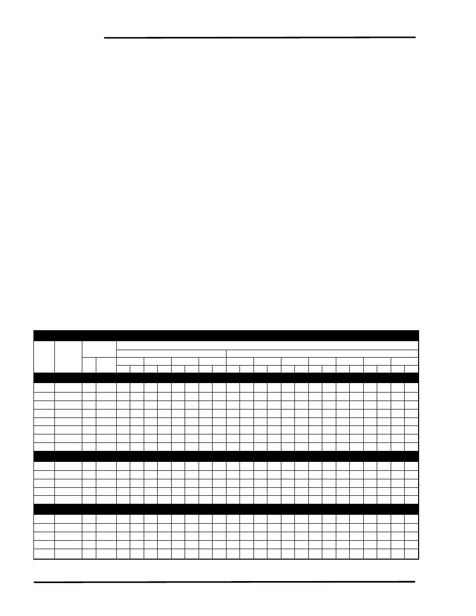
Refer to the nameplate on the unit for recommended fuse size. Table 6-1 relates the fuse size to
the appropriate branch size. A complete wiring diagram shown in Figure 12-1 is located inside
the door of the humidifier.
IMPORTANT: Please observe the following:
a. Make certain there is a manually operated interlocking circuit breaker or safety switch (not
furnished) in the electric service ACCESSIBLE TO AND WITHIN SIGHT OF THE
HUMIDIFIER.
b. USE ONLY WIRE WITH COPPER CONDUCTORS RATED 90°C OR HIGHER
FOR HIGH VOLTAGE AND GROUNDING.
c. Pass high voltage ground lead through provided ferrite core (AN) between where it enters
the cabinet and where it connects to ground lug.
d. Ground the humidifier cabinet; a ground lug is provided in the wiring compartment.
6
Table 6-1. Series EHU-700 Capacities and Electrical Ratings
Nom
Recommended
Output Per Hour @ Voltage Shown
Amp
Current Branch Circuit
Single Phase
Three Phase
Rating
Module
Wire
Circuit
120
208
240
277
208
240
346
1
380
415
2
480
600
Breaker lb
kg
lb
kg
lb
kg
lb
kg
lb
kg
lb
kg
lb
kg
lb
kg
lb
kg
lb
kg
lb
kg
EHU-701 Humidifier (One Small Steam Generator)
7
CM 7
14
15
2
0.9
4
1.8
5
2.3
6
2.7
7
3.2
8
3.6
12
5.4
13
6
15
6.8
17
7.7
21
9.5
12
CM 12
14
15
4
1.8
7
3.2
8
3.6
10
4.5
12
5.4
14
6.3
21
9.5
23 10.4 25 11.3 29 13.2 36 16.3
14
CM 14
12
20
5
2.3
8
3.6
10
4.5
11
5
15
6.8
17
7.7
24 10.9 27 12.2 29 13.2 34 15.4 42
19
16
CM 16
12
20
6
2.7
10
4.5
11
5
13
6
17
7.7
19
8.6
28 12.7 30 13.6 33
15
38 17.2 —
—
20
CM 20
10
25
—
—
12
5.4
14
6.3
16
7.3
21
9.5
24 10.9 35 15.9 38 17.2 42
19
—
—
—
—
24
CM 24
10
30
—
—
14
6.3
17
7.7
19
8.6
25 11.3 29 13.2 42
19
—
—
—
—
—
—
—
—
32
CM 32
8
40
—
—
19
8.6
22
10
26 11.8 33
15
38 17.2 —
—
—
—
—
—
—
—
—
—
40
CM 40
8
50
—
—
24 10.9 28 12.7 32 14.5 42
19
—
—
—
—
—
—
—
—
—
—
—
—
EHU-703 Humidifier (One Large Steam Generator)
20
CM 20
10
25
—
—
12
5.4
14
6.3
16
7.3
21
9.5
24 10.9 35 15.9 38 17.2 42
19
48 21.8 60 27.2
24
CM 24
10
30
—
—
14
6.3
17
7.7
19
8.6
25 11.3 29 13.2 42
19
46 20.9 50 22.7 58 26.3 72 32.7
32
CM 32
8
40
—
—
19
8.6
22
10
26 11.8 33
15
38 17.2 55 24.9 61 27.7 66 29.9 77 34.9 96 43.5
40
CM 40
8
50
—
—
24 10.9 28 12.7 32 14.5 42
19
48 21.8 69 31.3 76 34.5 83 37.6 96 43.5 120 54.4
48
CM 48
6
60
—
—
29 13.2 33
15
39 17.7 50 22.7 58 26.3 83 37.6 91 41.3 100 45.4 115 52.2 —
—
EHU-704 Humidifier (Two Large Steam Generators)
40
CM 20
8
50
—
—
24 10.9 28 12.7 32 14.5 42
19
48 21.8 69 31.3 76 34.5 83 37.6 96 43.5 120 54.4
48
CM 24
6
60
—
—
29 13.2 33
15
39 17.7 50 22.7 58 26.3 83 37.6 91 41.3 100 45.4 115 52.2 144 65.3
64
CM 32
4
80
—
—
39 17.7 45 20.4 51 23.1 67 30.4 77 34.9 111 50.3 122 55.3 133 60.3 154 69.8 192 87.1
80
CM 40
3
100
—
—
48 21.8 56 25.4 64
29
83 37.6 96 43.5 138 62.6 152 68.9 166 75.3 192 87.1 240 108.8
96
CM 48
2
125
—
—
58 26.3 67 30.4 77 34.9 100 45.4 115 52.2 166 75.3 182 82.5 199 90.2 230 104.3 —
—
NOTES:
1
346 Volt units require 346/200 volt 4-wire system.
2
415 volt require 415/240 volt 4-wire system.
KW rating = humidiity output (lbs/hr) x 0.345 (for energy calculations only; not for branch circuit sizing).