Armstrong World Industries EHU-703 User Manual
Page 11
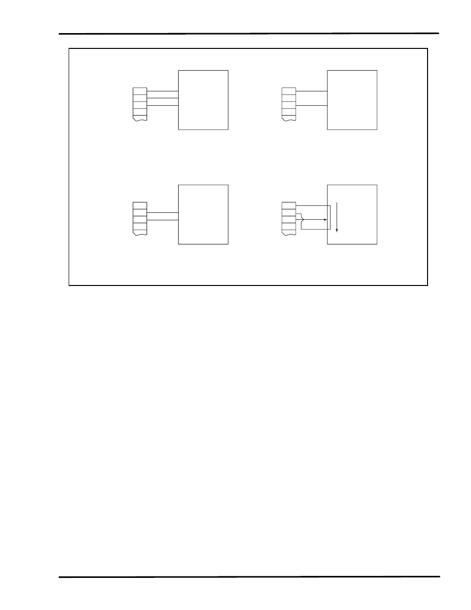
Duct Mounted Control Humidistat:
Duct-mounted control humidistats are also available for installation where sensing and control of return
air or exhaust air ducts is preferable. (Figure 10-1)
Please refer to manufacturer's recommendations for further information on the location, mounting, and
operation of the various control humidistats.
10) HIGH LIMIT DUCT HUMIDISTAT
Remove the jumpers tab from terminals 10 & 14 and wire the high limit stat between these
terminals. Refer to Figure 10-1 and Figure 11-1 (the overall wiring diagram) for more information.
A duct mounted high limit humidistat is recommended to prevent over-saturation of the duct air.
Use an on-off controller that opens on fault (high humidity). Humidistat should be set for a
maximum of 90% RH. Alternately, a modulation high limit humidistat may be used on applications
such as variable air volume (VAV). Locate the high limit humidistat approximately 10' (3m)
downstream of the dispersion manifold. If 10' (3m) is not available, consult the factory.
11) AIRFLOW SWITCH
An airflow switch is recommended to deactivate the humidifier when there is insufficient air flow in
a duct system. A duct pressure switch is preferred as an airflow sensor. The pressure switch
should open on insufficient airflow (opens on fault). Airflow switch should be mounted in supply air
duct upstream of humidifier dispersion. Remove the jumper tabs between terminals 9 & 15 and
wire the airflow sensor between these terminals. See Figure 11-1 and Figure 12-1 (the overall
wiring diagram) for more information. Complete installation and wiring instructions are contained
in the duct pressure switch package.
NOTE: LIMIT SWITCHES (HIGH LIMIT AND AIRFLOW SWITCHES) OPEN ON FAULT.
11
2
17
1
20
White
Black
Voltage Source
Ground
Stat In
N/C
Green
Part No.
C1471
or
C1472
2
17
1
20
Brown
Voltage Source
Ground
Stat In
N/C
Orange
Part No.
A8581
or
A8581A
2
17
1
20
-
Voltage Source
Ground
Stat In
N/C
+
2
17
1
20
Voltage Source
Ground
Stat In
N/C
Part No.
A6707A
or
A18611
Humidity
Increase
4-20 mA & 0-10 Vdc Setting*
Set BJ4 Stat Input Selector to
0-10 Vdc or 4-20 mA
0-135
Ω
Ohm Potentiometer
Set BJ4 Stat Input Selector to 0-135 Ohm
Set BJ5 Voltage Source to +5 Vdc
1.9 - 3.9 Vdc
Set BJ4 Stat Input Selector to 1.9 - 3.9 Vdc
Set BJ5 Voltage Source to 12 Vac
On-Off Humidistat
Switch Opens on RH Rise
Set BJ4 Stat Input Selector to On/Off
Set BJ5 Voltage Source to +5 Vdc
*See Figure 10-1 for Armstrong 0-10 Vdc Humidistat Connections
Figure 11-1