8 operating the sp-tune – Sony EBS-SP10 User Manual
Page 9
SP-TUNE User Manual
8
The respective audio input channels are selected when the corresponding video input is selected
(e.g., S-Video input).
Component RGB+HV or YPbPr video signal can be connected to the 15-pin male connector of SP-
TUNE:
- using the standard VGA cable for RGB+HV VGA signal;
- using the supplied adapter cable for YPbPr signal (Y=Green RCA, Pb=Blue RCA, Pr=Red RCA).
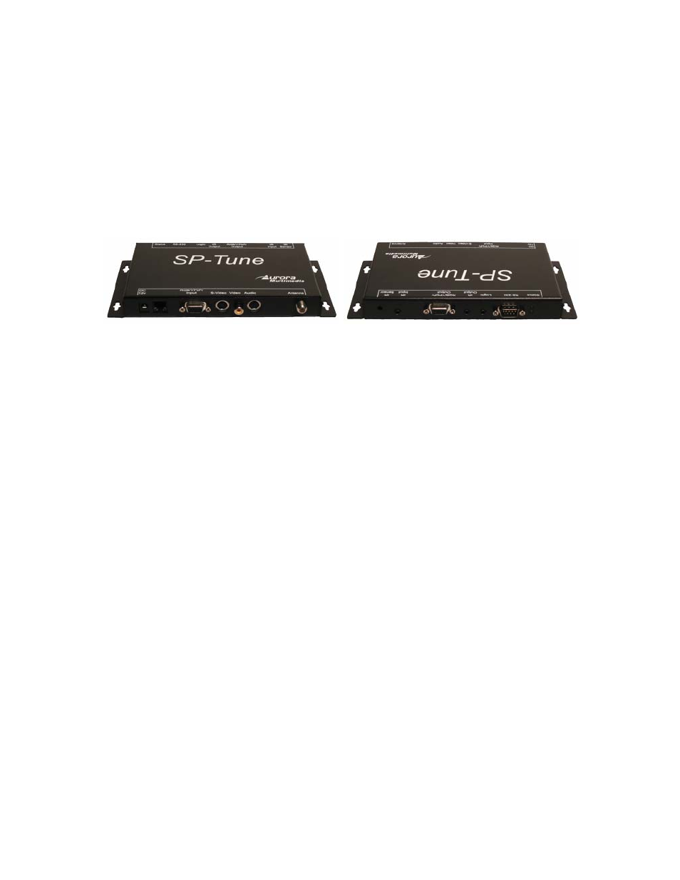
Different views of the SP-TUNE:
7.2 RF
connector
The coaxial connector (ANT) of SP-TUNE is RF signal input – either aerial or cable TV, UHF/VHF,
if the SP-TUNE shall be used as TV tuner.
7.3 RJ11 Service Port connector
RJ11 connector of SP-TUNE is used as a service port for Sony. Nothing should be connected to this
port.
Warning:
Damage may occur if plug into a different port such as a phone line. This will void the
warranty.
7.4 Power
connector
Connect the supplied 12v DC adapter to the power jack of the SP-TUNE unit.
Note that depending on pre-programmed settings the SP-TUNE can switch on automatically upon
attaching power supply, or remain in a “sleep” state.
It is recommended to connect the power supply only after all other connections are done.
8 Operating the SP-Tune
The SP-TUNE has many advanced features to enhance the typical viewing and usability of a TV
Tuner.
A user can switch the unit on or off, control volume level, switch the current TV channel, either
directly entering channel number, or browsing through valid channels using Channel +/- keys (usually
Arrow Up/Down key on a remote controller). “Valid” channels are the channels where a valid TV signal
was discovered during recent “channel scan” operation (in stand-alone mode).
Since the SP-TUNE allows to attach several additional video signal sources to its AV inputs, to
facilitate user selection of these inputs SP-TUNE maps some additional “channel numbers” to its AV
inputs. So when a user selects one of these “channels”, the SP-TUNE switches to the respective AV input.