Ch.5 jumper and connector locations, Top view, Jumper and connector locations – Aspire Digital 1360 User Manual
Page 107: Chapter 5
Chapter 5
98
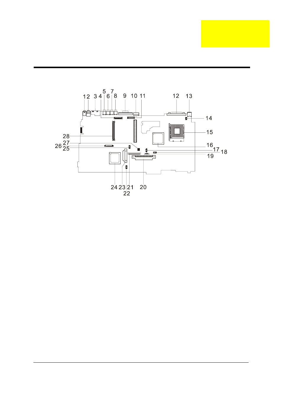
Top View
1
LIN1
Line-in Port
15
U11
CPU Socket
2
LOUT
Line-out Port
16
U16
North Bridge
3
JK1
RJ45+RJ11
17
FAN1
Fan Connector
4
INV1
LCD Inverter Cable Connector
18
Note: There is no 18 on this main board.
5
CN1
USB Port
19
TPAD1
Touchpad Cable Connector
6
CN2
USB Port
20
HDD1
HDD Connector
7
CN3
USB Port
21
KB1
Keyboard Connector
8
CN4
USB Port
22
SPK1
Speaker Cable Connector
9
CRT1
VGA Port
23
IDE1
Optical Drive Connector
10
TV1
S-Video Port
24
U26
South Bridge
11
LCD1
LCD Coaxial Cable Connector
25
CN9
RTC Battery Connector
12
PRT1
Parallel Port
26
CN8
Launch Board Cable Connector
13
DCIN1
DC-in Port
27
SW1 (Please see Chapter 5 for its settings)
14
CN6
LCD Lid Switch
28
SKT1
PCMCIA Slot
Jumper and Connector Locations
Chapter 5
This manual is related to the following products: