Hardware setup, 1 tusl2-c motherboard layout, 14 asus tusl2-c user’s manual – Asus INTEL TUSL2-C User Manual
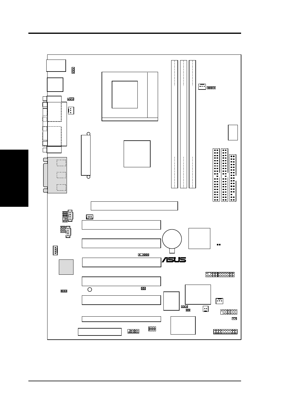
Page 14: Socket 370, Pci1 pci2 pci4 pci3, Pci5, Tusl2-c, Accelerated graphics port (agp), Super i/o, Intel 815ep chipset
14
ASUS TUSL2-C User’s Manual
3. HARDWARE SETUP
3.1 TUSL2-C Motherboard Layout
PS/2KBMS
T: Mouse
B: Keyboard
PWR_FAN
GAME_AUDIO
Mic
In
Line
Out
Line
In
PCI1
PCI2
PCI4
PCI3
PANEL
IDELED
FLOPPY
SECONDAR
Y
IDE
PRIMAR
Y
IDE
TUSL2-C
CHA_FAN
CD
AUX
®
PLED2
Accelerated Graphics Port (AGP)
CR2032 3V
Lithium Cell
CMOS Power
DIMM1 (64/72 bit, 168-pin module)
1
0
DIMM2 (64/72 bit, 168-pin module)
3
2
CLRTC
DSW
Socket 370
AUDIO_EN
USB
T: Port0
B: Port1
PCI5
CNR_SLOT
C-Media
PCI
Audio
Super
I/O
CPU_FAN
Firmware
Hub
(FWH)
MODEM
CHA
WOL_CON
WOR
AAPANEL
MIC2
HPHONE
JEN
AFPANEL
DIMM3 (64/72 bit, 168-pin module)
5
4
DIP
Switches
PCI6
ASUS ASIC
with
Hardware
Monitor
VIO
Intel I/O
Controller
Hub
(ICH2)
Intel
815EP
Chipset
USBPWR01
KBPWR
SMB
USBPWR56
USBP56
SMARTCON
IR_CON
JTPWR
OC3
COM1
P
ARALLEL
POR
T
COM2
A
TX Power Connector
Motherboard Layout
3. H/W SETUP
Grayed components are optional at the time of purchase.