0 installation, 01 setting the option switches – ADTRAN NT1 T400 User Manual
Page 12
61212016L1-1
NT1 T400 User Manual
3
2.0 INSTALLATION
After unpacking the unit, immediately inspect it for possible ship-
ping damage. If damage is discovered, file a claim immediately
with the carrier, then contact ADTRAN Customer and Product
Service (CAPS) Department at the number listed in the back of the
manual.
2.01
Setting the Option Switches
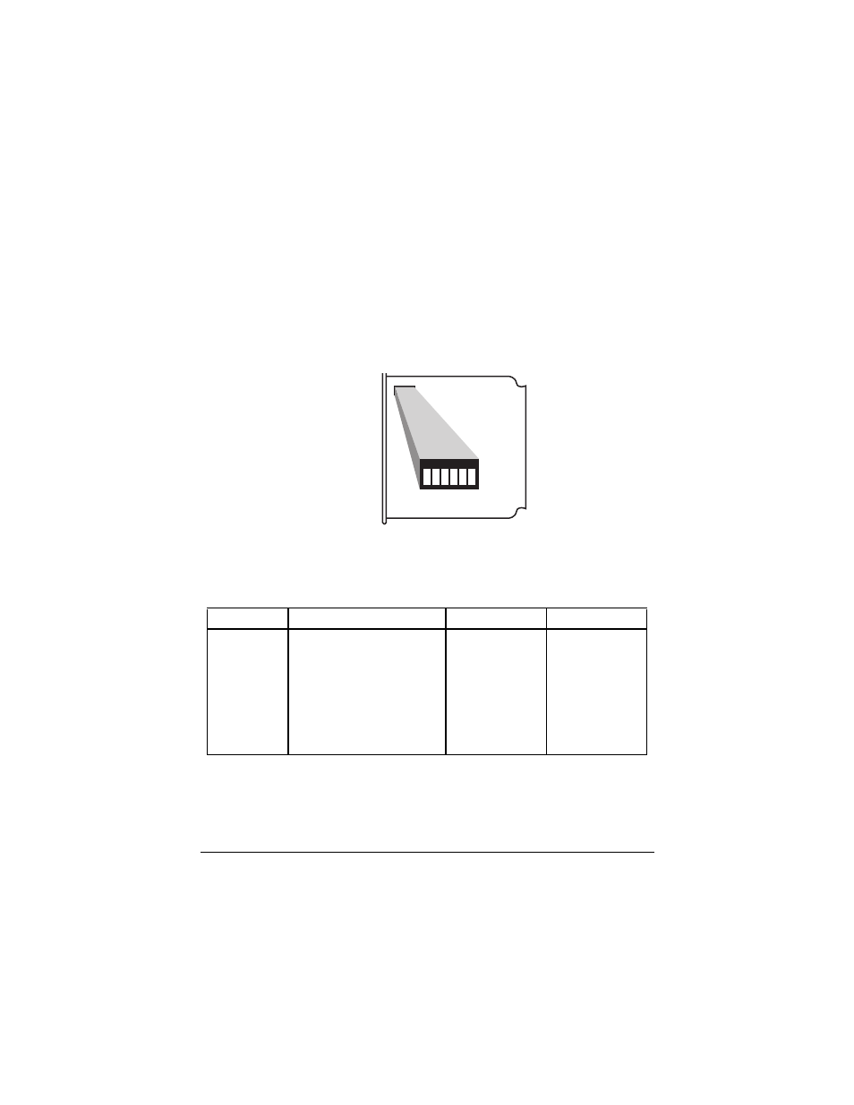
Remove the Circuit Pack from the NT1 Standalone housing by re-
moving the plastic front panel and sliding the Circuit Pack out of
the front of the unit. Figure 2 illustrates switch option locations;
Table 2 lists the function of each switch.
Figure 2: NT1 Type 400 Switch Option Locations
Table 2: NT1 Type 400 Switch Settings
Refer to Appendix B to determine what type of bus and termina-
tion applies to your installation and to set the switches according-
ly.
Switch
Description
On
Off
6
50 ¾ termination
50 ¾
None
5
50 ¾ termination
50 ¾
None
4
100 ¾ termination
100 ¾
None
3
100 ¾ termination
100 ¾
None
2
Long or short passive bus
Long
Short
1
Future use
N/A
N/A
SW1
FRONT
1
2
3
4
5
6